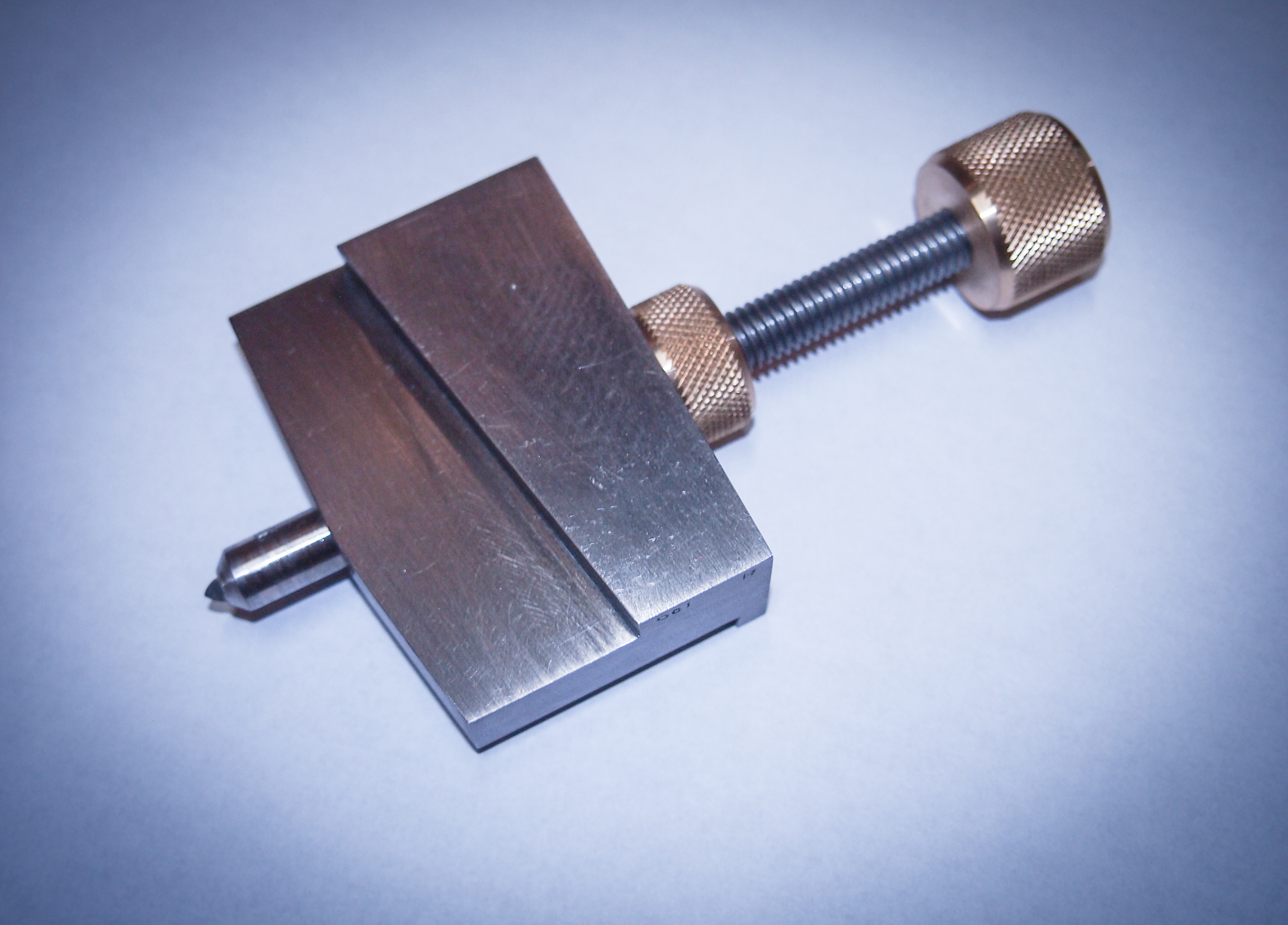
You thinking something like this?
Sort of, but the picture above the tool is for a bench grinder. The raised edge goes against the bench grinder rest which is very close to the wheel. For my grinder, the reference is the slot in the table. It is machined, whereas the actual edge of the table is a rough casting. I need to make a tool which rides in the 12 mm wide slot in the table. That isn't too hard. I just need to make the fixture a bit larger more like 3-4 inches long to get from the slot (which is the reference edge) to the wheel.
The screw appears to be for advancing the point. What I don't see is how the point is captured, or prevented from rotating. Is this just as simple as a screw pushing out the (loose) point into the wheel? I could make something like this. Would take a piece of 1 x 1.5 6061 and some 1/4" screw and something for the lock nut and turn knob. Think I have some 1/4-28 all thread.
I was envisioning something more complicated which holds the bit in some sort of piston, which is moved by a fine pitch (or differential) screw. I've made differential screws before, might make a 1/4" diameter 24 TPI / 28 TPI screw. That would give about 0.006" positioning per turn. I made a similar screw to position my tail stock on my mini-lathe. I could single point the threads on the rod. I believe one can get 1/4"-24 TPI taps. There's a captured nut, which when spun, that gives some coarse adjustment. The assembly is a housing, a coarse captured nut, a dual threaded rod, and a fine threaded piston. The piston has a recessed set screw to hold the tool. The housing is bored out for the piston (easy) and the captured nut. Can't figure out how to make a curved slot for the nut yet, but I could always just mill a flat slot. Haven't decided if I need a key for the piston or not. Guess I could drill through the housing and install a pin, or a pin held in place by a set screw. I could run a slot down the piston with a slitting saw. To rotate the diamond, I would remove the piston, relax the set screw and rotate the bit relative to the piston.
Of course this concept paragraph is a little over the top, but hey, it seems like it would be fun to make. In some of the literature that I have read, it is recommended that the diamond is only moved inwards a few thousandths at a time for a pass. A differential screw makes this easy 1/4T = 0.0015". For a 1/4-28, 1T = 0.036", so we are talking about moving the knob 1/16T per pass (0.0022").


 An ordinary piece of 3/8" rod does, since the piece I just picked up was 0.373" I hand turned a "V" drill in the hole (0.377), ruining the reamed finish, hoping to open it up a little, but still doesn't quite fit.