Design and build of a Rear Mount Parting Tool for a G0752Z (G0602) Lathe

WobblyHand

H-M Supporter - Diamond Member
H-M Lifetime Diamond Member
Joined
Dec 18, 2019
Messages
6,464
I don't want to clutter up @Pescadora's thread with my project, so I thought I would start one of my own. Been very attracted to parting with little trouble. Parting is great when your lathe is set up just so, but on occasion, weird stuff happens and parting becomes a horror show. This just recently happened, so I am ready to make something to mount on my G0752Z lathe. I like the idea of taking the compound out of the picture for this. It's also great to take out the need for adjusting all the degrees of freedom that contribute to a bad parting session. So taking the plunge. This first part of the thread is about the design, and measuring the correct offset of the blade.

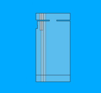
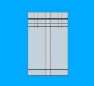
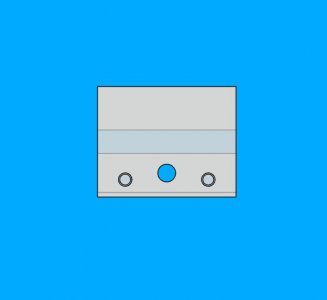
@mikey has suggested some basic design elements that one should adhere to, namely a double opposed slit. Honestly, I'm on the fence on the need for it, but think for this pass, I will go with his recommendation. I can always change the design and make a different one! I have modeled the parting tool holder for a 1/2" blade. If people want, I can post the FreeCAD file for this. I used spreadsheet based design for this, so it should be pretty easy to adapt to your own lathe. Of course, you will have to know FreeCAD, but if I could learn it, you can too!

The holder is made from a piece of 2 x 2.5 x 4 inch 6061, because I have a chunk of metal that is 2x2.5x6. I am using an M8 for the hold down to the cross-slide and two M6 screws as additional blade clamps. The M8 hole is spaced at 11mm from the edge, which is about midpoint of the thickness available to drill in my cross-slide. Here are a couple of views of what I have so far. No technical drawings with full dimensions yet, but all of the dimensions are in the model. Kind of goofed up with the bottom, it used to have a mounting flange, but I took it out. This is one single block.
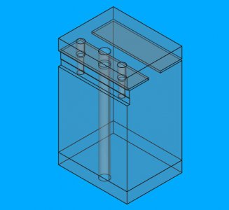
parting_plinth_oblique.jpgparting_plinth_right.jpgparting_plinth_front.jpgparting_plinth_top.jpg
I am going to have fun drilling the M8 through hole as my drill bits are not long enough. Any tips on flipping the piece to drill through? Any thoughts on design changes?
 
I would buy a longer drill bit. I have had poor luck having holes line up when drilling from both sides. Even if laid out accurate the drill bit may wonder enough not to line up.
 
I would buy a longer drill bit. I have had poor luck having holes line up when drilling from both sides. Even if laid out accurate the drill bit may wonder enough not to line up.
Would be nice to find one. I need a P drill that can drill 4". Best I can find so far is an extended P drill with a max drill depth of 3.64" according to McMaster. The drill is longer though. Could I peck through the last 0.36"?
 
Do you have a reamer?
If you have to drill from both sides, use a vise stop, and locate the hole on center. Also use a center drill on both ends. That should work fine with no adjustments of table position when you flip the part.
You could also counter bore it. Or go up one size on the opposing side. There's not a requirement that I can see for the hole to be one size throughout its length. It's just clamping it down.
 
Last edited:
Do you have a reamer?
If you have to drill from both sides, use a vise stop, and locate the hole on center. Also use a center drill on both ends. That should work fine with no adjustments of table position when you flip the part.
You could also counter bore it. Or go up one size on the opposing side. There's not a requirement that I can see for the hole to be one size throughout its length. It's just clamping it down.
No letter reamers. The only reamers I have are 1/4, 3/8, and 1/2".

Agreed, it doesn't have to be one size all the way through. That makes it easier and cheaper for me to make.
 
I am assuming that your plan is to remove the compound and replace it with your rear parting tool using the OEM L.H. threaded hole and that you will part running the lathe in the forward direction with the tool upside down.

The OEM hole doesn't extend much, if at all , past the centerline of the spindle. In order to use a rear mounted parting tool, you will have to drill and tap a new mounting hole. The double slit offers no advantage. You can cut the back tab off completely with no effect. In fact, it will cause a disadvantage. The clamping force will be determined by the ratio of the distance from the flexure point to the clamping screws divided by the distance from the flexure point to the parting tool. As designed, the ratio will always be less than one but increasing the length of the slit will make it closer to one. I would eliminate the back slit and make the front slit deeper. for the greatest mechanical advantage.

I am also concerned about the fasteners. Cutting forces when parting from the rear are directed upward, placing additional tensile stress on the clamping screws and the mounting screw. Conceivably, they could be enough to shear the screws. Worst case, you could shear the threads in the cross slide.

I don't want to rain on your parade, just to give some food for thought. I have done quite a lot of modification on my G0602 and have gained some experience with it.
 
I won't argue about what features of my personal design are necessary. All I can tell you is that it has functioned perfectly for a very long time. Two 10-32 SHCS screws have not pulled out and are more than sufficient to hold the blade solidly, no cracking has occurred anywhere, and it has been held down to an aluminum cross slide with a single screw threaded into a steel T-nut and nothing has broken in over a quarter century. You can overbuild it and that would be fine, too.

There are only two critical things that you must attend to: the bottom of the slot must be on the spindle centerline and you should incorporate a ledge at the bottom to bear against the side of the cross slide. As long as the ledge is used then a single bolt will lock the tool post solidly. If you thread the hole for this locking screw the full thickness of the cross slide then it should hold without cracking anything. As I said before, the lock down screw can be countersunk inside the body of the tool post.
 
I am assuming that your plan is to remove the compound and replace it with your rear parting tool using the OEM L.H. threaded hole and that you will part running the lathe in the forward direction with the tool upside down.
No. I probably will remove the compound, because it may get in the way, but I will mount the plinth so it is along the rear of the cross-slide and along the edge facing the headstock. I will put in a locating feature along the long edge so the plinth and parting blade are perpendicular to the spindle. The blade will be upside down pointing towards the operator. The spindle will run in the normal forward direction.
The OEM hole doesn't extend much, if at all , past the centerline of the spindle. In order to use a rear mounted parting tool, you will have to drill and tap a new mounting hole. The double slit offers no advantage. You can cut the back tab off completely with no effect. In fact, it will cause a disadvantage. The clamping force will be determined by the ratio of the distance from the flexure point to the clamping screws divided by the distance from the flexure point to the parting tool. As designed, the ratio will always be less than one but increasing the length of the slit will make it closer to one. I would eliminate the back slit and make the front slit deeper. for the greatest mechanical advantage.
I have mixed feelings on the double slit. I was thinking of a longer single slit with a hole, like looking at a lollypop which should reduce stresses at the end of the slit. @mikey is a proponent of the double slit, which has worked for him. 25 years of success is a very good run, so it is tough to argue with that. Aesthetically, though, it looks weird, I have to confess.
I am also concerned about the fasteners. Cutting forces when parting from the rear are directed upward, placing additional tensile stress on the clamping screws and the mounting screw. Conceivably, they could be enough to shear the screws. Worst case, you could shear the threads in the cross slide.
I was going to use an M8 Grade 12.9 SHCS for the main hold down. Supposedly the screw is good for 170,000 lbs in tensile strength. The smaller clamp screws would be M6 also Grade 12.9. The M8 would be threaded into the headstock side of the cross-slide, about 11 mm from the long edge, and about midpoint of the plinth. The cross-slide is roughly 22mm wide at that point, so the hole should be roughly midpoint between the vertical edge and the dovetail.
I don't want to rain on your parade, just to give some food for thought. I have done quite a lot of modification on my G0602 and have gained some experience with it.
All thoughts are welcome. I have read quite a few of your threads on the G0602 and think you are both methodical and talented. Of course, at some point, I am going to have to grow up, spread my wings at some point, and try some things out. There's no guarantee of success when you try something new, but sometimes you have to try in order to learn. But, yes, I am still listening and attempting to sort things out. I definitely want to know if I am attempting to do something hazardous to my health.

As this is still in design stage, I can still play around with a couple of ideas. Once I know what I am doing, the execution phase doesn't take long.

I can take a picture of the location of the plinth and the approximate hole placement in the cross-slide if it wasn't clear from my description.
 
I also like a lollipop flexure cutout.
 
I just looked up the ultimate tensile load for M6 and M8 fasteners and I would agree they should be up to the task. Almost 6,000 lbs for a grade 12.9 M6. My concern was rooted in the dive that I have seen when a parting tool digs in. A lot depends upon the available torque from the lathe motor.

If you are drilling and tapping a hole for a rear mount, you should consider going whole hog and making a complete set of mounting holes for the compound. I did that for my 602 when I made the improved compound clamp.

I will be interested in seeing your results. I looked at rear mounted parting and concluded that it was too much bother as I would have to move the compound to a rear position and my AXA parting tool holder wouldn't work . A direct mounting on the cross slide would change the game. I already have the mounting holes and for much work, I wouldn't have it remove it or the AXA tool post.
 
Back
Top