Design and build of a Rear Mount Parting Tool for a G0752Z (G0602) Lathe

Go ahead with the upload. I thought that I had done so with the SolidWorks files but apparently not. I used to belong to the Yahoo 10 x22 group and believe that I had posted the files there but Yahoo groups have disappeared. I would mention that the clamp kit is available from Peter Belfonti. Here is the last email address that I had for him. peterbelfanti@yahoo.com

You might add this link as there is some additional information in this thread.https://www.hobby-machinist.com/threads/improved-g0602-compound-clamp.34796/
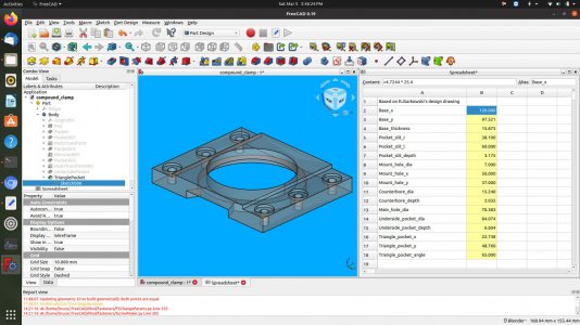
Thanks for the permission. Now to figure out the upload process... At the moment, I only have the solid model. It will take me a little bit to make the technical drawings. Don't think they will be as nice as yours, as 1) this is freeware, and 2) I'm a novice operator. Nonetheless, there is a built in spreadsheet with all the dimensions embedded with the drawing as well which can be consulted. A FreeCAD conversant person should be able to decipher it.
 
Thanks for the permission. Now to figure out the upload process... At the moment, I only have the solid model. It will take me a little bit to make the technical drawings. Don't think they will be as nice as yours, as 1) this is freeware, and 2) I'm a novice operator. Nonetheless, there is a built in spreadsheet with all the dimensions embedded with the drawing as well which can be consulted. A FreeCAD conversant person should be able to decipher it.
I have my drawing as a SolidWorks drawing and a DXF drawing. If you model is essentially a copy of my model, you should be able to convert it.
 

Attachments

  • Lathe Compound Clamp.DXF
    125.1 KB · Views: 7
I have my drawing as a SolidWorks drawing and a DXF drawing. If you model is essentially a copy of my model, you should be able to convert it.
Thanks. With a little fiddling I was able to import the DXF. Looks like my model. FreeCAD doesn't do this import elegantly - or more likely, I don't know how to drive the tool. Only learned it this year. It would be tedious to start from this dxf, as none of the dimensions seem to be preserved. I can see the lines, but the measurements are off. All I get are objects called shapes. But no quantifiable information, like diameter, or even length of a line. If I measure the endpoints of a line, I get lengths which make no sense. The width of the part from the imported DXF measures to 1524.000 mm! (60"). Your part is actually 120 mm (4.7244") wide. So either FreeCAD has got a bad importer, or I don't know how to use it! I could try a 2D program, but this isn't worth playing around with, at least it isn't to me.

My model was created from your drawing posted in your thread. Start to finish was under 2 hours. The only odd thing was the units conversion, rather precision. My drawing is in mm. So rather than using 49.99999 mm, I rounded it to 50. Save for some 5th and higher digit right of the decimal point, these models are the same (to the best of my knowledge).

This is a copy of the spreadsheet in the FreeCAD file, the program looks here to find the basic dimensions, and draws the model. As you can see, it's more or less, just converting to metric. Essentially these are constraints on the model which are used. Sorry about the formatting, the forum sw is pretty bad with tables!

Code:
Based on RJSarkowski's design drawing   
Base_x            =4.7244 * 25.4
Base_y            =3.8394 * 25.4
Base_thickness    =5 / 8 * 25.4
Pocket_slit_r    =1.5 * 25.4
Pocket_slit_l    =Base_x / 2
Pocket_slit_depth    =0.125 * 25.4
Mount_hole_dia    =0.2756 * 25.4
Mount_hole_x    =1.9685 * 25.4
Mount_hole_y    =1.4567 * 25.4
Counterbore_dia    =0.6 * 25.4
Counterbore_depth    =0.08 * 25.4
Main_hole_dia    =2.771 * 25.4
Underside_pocket_dia    =3.31 * 25.4
Underside_pocket_depth    =0.26 * 25.4
Triangle_pocket_x    =Base_x / 2 - 1.467 * 25.4
Triangle_pocket_y    =Base_y / 2
Triangle_pocket_angle    65
 
@RJSakowski, just successfully uploaded the FreeCAD file of your compound clamp, with attribution and links to your thread. Tags are g0602, g0752 and compound clamp.
 
Last edited:
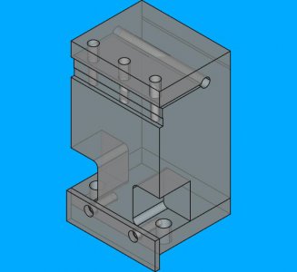
Back to the rear parting tool. So far this is what I have. Added an additional M8 mounting hole to the base. Felt uncomfortable with only one bolt. Two bolts will resist the upward movement of the blade better than one. Eliminating the central long (120mm) M8 through bolt allowed me to add a third M6 bolt to captivate the parting blade. Had to make pretty big pockets to be able to fit the M8 bolts. Hope they are tall enough to actually extract the bolts, and give me enough room to get a hex key in. Toyed with using a hex head bolt, but then I would need to make the pocket wider to fit a wrench.
rev2_oblique.jpg
Been recently alerted to the issue of maintaining the verticality of the parting blade. It seems blades are somewhat standardized. Some have 2 degree angles, 2 blades I measured were about 0.18 degrees, and 1 blade was 0.39 degrees, there might be some that have true square sides. Doesn't feel standardized, but maybe I shouldn't be buying cheap blades!

This means the blades could be canted in the holder. It would be nice to have a built in feature for the blade to register against to ensure the blade is vertical. Not sure if this is necessary, but the whole point of this tool holder is to make sure the blade is 1) 2D orthogonal to the spindle, (right angle to spindle axis, and right angle vertical to spindle axis) and 2) parallel to the cross-slide travel. Have to think if this matters much to me.
 
After some thought, I think I will proceed with the design above. Here are some pdf drawings I have made for this design (so far). 1 pdf per page. For those that have FreeCAD, I can attach the file, if desired. Hope my technical drawings are not too difficult to follow. Think everything is dimensioned. Heh, still working on my style. Fasteners are M6 on the top for blade clamp, M8 on the bottom to clamp to the cross-slide, and M6 for the cross-slide alignment plate. I think this is within my ability to execute. Will find out in a while.
 

Attachments

  • G0602RearMountPartingToolpage1of5.pdf
    219.3 KB · Views: 1
  • G0602RearMountPartingToolpage2of5.pdf
    233.9 KB · Views: 0
  • G0602RearMountPartingToolpage4of5.pdf
    216.8 KB · Views: 0
  • G0602RearMountPartingToolpage5of5.pdf
    221 KB · Views: 1
  • G0602RearMountPartingToolpage3of5.pdf
    231.6 KB · Views: 1
Recently acquired a nice chunk of steel for this rear parting tool. I was willing to slit a piece of aluminum to 30mm deep, but I don't want to do this with a piece of steel.

About a month ago, I made a 30mm diameter mandrel from 1045 steel and cut 3 slots in it, 1" deep. It took a couple of hours to cut the slots on my mill. The mill kept stalling because it had insufficient torque at the low speed necessary for a 4" diameter saw. So I think I may change the parting tool design to a separate top plate, held down by 3 M8 screws. I suppose I could make a new pulley for the mill, but I don't want to tie up this project on making a pulley.

I measured my spindle centerline height from the cross-slide and found it to be 3.0495". I was working on my spindle replica for my back plate, and had turned the section true. I used a couple 123 blocks stacked, and then stacked some shims to just below interference with the turned rod in the chuck. I then measured the rod diameter with the micrometer. Then added the 1/2 the rod diameter to the 123 blocks + shim height. This dimension, (77.437mm) was slightly less than the 79mm I had used in the FreeCAD model. So I updated the model. While I was at it, I updated the model with the dimensions that are a little closer to the steel block dimensions.
 
Back
Top