Design and build of a Rear Mount Parting Tool for a G0752Z (G0602) Lathe

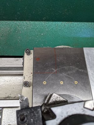
Here is the rough location of the plinth. Marked the cross-slide in red. Top left corner.
PXL_20220305_013214488.jpg
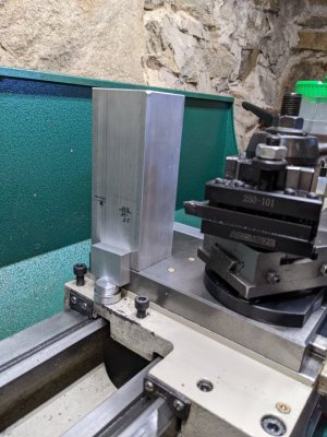
Here is the plinth body (unmachined and too tall) and a rough idea of the locating feature. I suppose I could put something in back, but it is probably not necessary. Ignore the scrap I used to hold up the locating block. Couldn't find a prettier spacer :)
PXL_20220305_013545009.jpg
If you are drilling and tapping a hole for a rear mount, you should consider going whole hog and making a complete set of mounting holes for the compound. I did that for my 602 when I made the improved compound clamp.
Can you explain that? I mean, the cross-slide will be off the lathe and on on the mill, so more holes would be easy. Yeah, it will take me some time to make a drawing, but that's easy. Do you have a thread on the compound clamp?
 
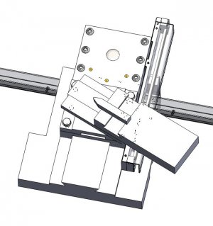
Here is the SolidWorks assembly model. Ignore the DRO scales.
View attachment 399122

See also: https://www.hobby-machinist.com/threads/have-you-ever-tried-this.95436/page-2#post-888037 Post #11 I machined the secondary compound holes when I had the cross slide off for the DRO modification. I should have a dimensioned drawing of the holes. The middle holes correspond to the OEM mounting holes while the corner holes match my improved compound clamp.
Thanks! I will take a look at this. Appreciate your posting. The compound is a bit flexy under duress. That modification looks like it would help. My G0752Z came with DRO's so, I don't have to ignore them! Located in same area.
 
Thanks! I will take a look at this. Appreciate your posting. The compound is a bit flexy under duress. That modification looks like it would help. My G0752Z came with DRO's so, I don't have to ignore them! Located in same area.
The six bolt compound clamp greatly increased the rigidity of the compound. Much of the problem with parting had to do with the flimsy nature of the compound clamp. I designed one first for the Grizzly G4000 and when I bought my G0602, it was one of the first modifications that I made. There is kit for it based on my design being sold You might want to consider this mod while you have everything apart. It corrects another weak point with the compound. https://www.hobby-machinist.com/threads/g0602-compound-protractor-calibration.35295/
 
On another note, you might consider foregoing the slit in favor a secondary plate bolted to the top of the plinth. It will make machining easier and you can add a top groove to keep the parting tool vertical. There would be no need for the lollipop then although a thinned section for a flexure joint would be a good feature.
 
I used threaded rod for my clamping bolt. Note my parting tool holder is cast iron with a fairly beefy (for an Atlas) cross slide. But something I was taught once, was that everything will have a weak point. Try to design it so that you choose the weak point, and it's failure won't be catastrophic. Breaking the clamp bolt seems to me, a very recoverable failure. The parting tool will lift out of the cut, and you replace your threaded rod. No cracked or broken machined components and no explosions of hss. Just a stretched or bent rod. Something to consider anyhow.
 
The six bolt compound clamp greatly increased the rigidity of the compound. Much of the problem with parting had to do with the flimsy nature of the compound clamp. I designed one first for the Grizzly G4000 and when I bought my G0602, it was one of the first modifications that I made. There is kit for it based on my design being sold You might want to consider this mod while you have everything apart. It corrects another weak point with the compound. https://www.hobby-machinist.com/threads/g0602-compound-protractor-calibration.35295/
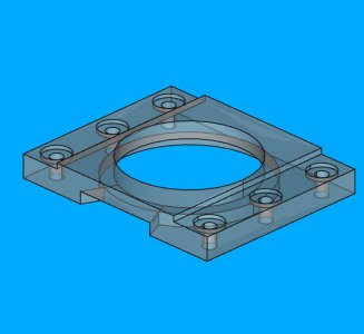
Found your drawing of the compound clamp. Made a model in FreeCAD this morning. Didn't take too long to recreate. Have to re-read the protractor calibration thread. Very informative, but not easy for me to follow late at night.

Do you mind if I upload my FreeCAD model of the compound clamp to HM? Perhaps someone could benefit from it.
rjsarkowski_compound_clamp.jpg
 
I used threaded rod for my clamping bolt. Note my parting tool holder is cast iron with a fairly beefy (for an Atlas) cross slide. But something I was taught once, was that everything will have a weak point. Try to design it so that you choose the weak point, and it's failure won't be catastrophic. Breaking the clamp bolt seems to me, a very recoverable failure. The parting tool will lift out of the cut, and you replace your threaded rod. No cracked or broken machined components and no explosions of hss. Just a stretched or bent rod. Something to consider anyhow.
That's an interesting idea, very much like a shear bolt. It stinks when a shear bolt breaks, but it's far better than destroying an expensive part. I will definitely consider this.
 
Found your drawing of the compound clamp. Made a model in FreeCAD this morning. Didn't take too long to recreate. Have to re-read the protractor calibration thread. Very informative, but not easy for me to follow late at night.

Do you mind if I upload my FreeCAD model of the compound clamp to HM? Perhaps someone could benefit from it.
View attachment 399136
Go ahead with the upload. I thought that I had done so with the SolidWorks files but apparently not. I used to belong to the Yahoo 10 x22 group and believe that I had posted the files there but Yahoo groups have disappeared. I would mention that the clamp kit is available from Peter Belfonti. Here is the last email address that I had for him. peterbelfanti@yahoo.com

You might add this link as there is some additional information in this thread.https://www.hobby-machinist.com/threads/improved-g0602-compound-clamp.34796/
 
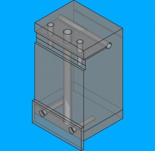
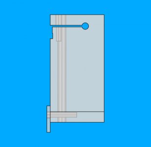
Made some edits to the parting tool. The lollipop is back. I made the slit 30mm long and used a 6.35mm drill hole at the end. The deepest I can cut is 32 mm, so 30 mm keeps me from bumping the saw arbor. But, due to the lollipop, the slit is effectively 6 mm longer. Think this will be ok. An ordinary jobber length drill isn't quite long enough to drill through the 2.5", however, there are quite a few extended length 1/4" drill bits that would work. Here's a couple of views of the piece. This piece will be made from 6061, as my mill would really struggle to cut deep slots in steel! I just recently added a 1/8" thick steel locating plate to the drawing, using M6 screws to hold it in place.

The novelty of being able to make these drawings hasn't worn off yet. I've struggled for decades with 3d CAD. It's only this year, I have been able to learn this. Guess it is a small, personal triumph. Still makes me giggly. What's really nice is everything (in this drawing) is composed of pretty easy primitive operations. Everything you see here is made of simple sketches, pads and pockets.
nearly_done_oblique.jpgnearly_done_right.jpg
The blade slot is for 1/2" high blades, up to 3/32" thick. I could easily adapt it to accept an 1/8" blade, but not sure if that's a good idea for this lathe.
 
Back
Top