- Joined
- Dec 18, 2019
- Messages
- 6,447
As @davidpbest noted, you might consider taking it apart to study how it works. He has excellent advice. He posted as I was writing this.
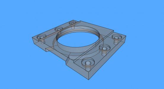
On my (smaller) lathe I have a compound clamp that will hold the compound in any direction. I made it based on the design by @RJSakowski . It uses studs and nuts which can be accessed in any position. The studs are below the compound. The nuts are recessed slightly. I can loosen the six nuts and have room for a wrench to tighten them. On the right, in black oxide, is the original compound clamp. It is much lighter and flimsier.
Don't think your tee nut issue will be too tough to solve.