DoAll G-10 Surface Grinder

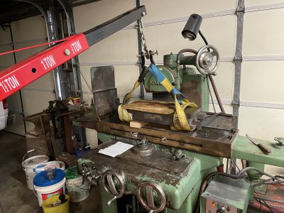
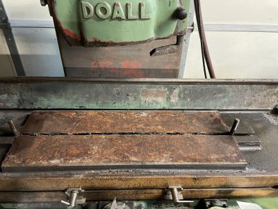
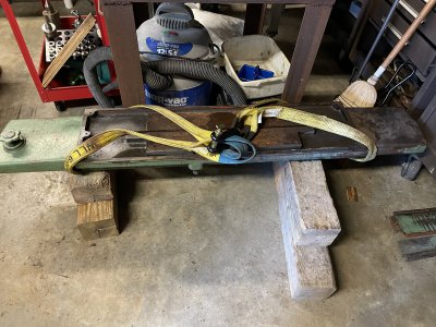
Well first it was a bit of a chore getting it off of the trailer when I got home. My tractor wouldn’t handle it and I have used a tow truck driver to pick heavy stuff off of the trailer in the past. Somehow I cheezed him off and he wouldn’t show up. I don’t mind cheezing someone off but I prefer to do it on purpose. Anyway my neighbor has a bigger tractor with a grappling attachment that acts like a built in spreader bar to set it off with. I then used my tractor to duck walk it in the shop. The stinkin’ thing is heavy with very little in the way of purchase points to handle it.

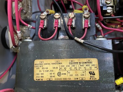
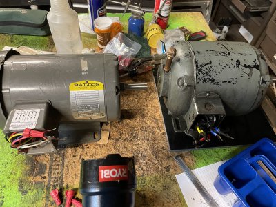
After I got it set in place I went through the electrical box to check the motor starters to gain some confidence that it was in fact expecting 240 volt, 3 phase power. I found a big transformer that stepped the 240 volts down to 120 volts and the only thing I can find that it runs is the worklamp.
 

Attachments

  • D1717E22-6EC0-453C-83A0-6FE729BC204C.jpeg
    D1717E22-6EC0-453C-83A0-6FE729BC204C.jpeg
    546.2 KB · Views: 63
I applied power and almost immediately the hydraulic motor started smoking. The fella ran it for me in Nashville and seemed to do fine. The interstate system in Nashville is rough on your dentistry so I figured I had sloshed some of the three gallon lake of hydraulic oil in the bottom of the cabinet into the motor. It’s appearance seemed consistent with the idea. So I removed the pump and the filter to get at the motor, disassembled it, cleaned it as much as I dared with contact cleaner and put it all back together. It still smoked. I ran it enough to measure the hydraulic pressure and the RPM, 280 psi and 1750 RPM respectively. Somewhere I read that the pressure was supposed to be 250 psi +/- 50 psi so it seems the Tuthill pump was doing OK. So I started trolling the EBay in search of a replacement motor and found one and ordered it.
 

Attachments

  • 1F2E50D4-FAC1-44E6-BC94-6989666D3C56.jpeg
    1F2E50D4-FAC1-44E6-BC94-6989666D3C56.jpeg
    464 KB · Views: 52
  • 968BBF2A-B731-4683-97A7-6AE2FF62D340.jpeg
    968BBF2A-B731-4683-97A7-6AE2FF62D340.jpeg
    464.5 KB · Views: 57
Since I had to wait on the new motor it seemed time to go through and clean the hydraulic tank. The tank is divided in halves. The left side was the return side of the system and is where the oil is added and drained. The other side is where the intake screen for the pump is located and the return from the oil filter. The divider between the two sides has a 1 1/2 in hole to allow oil to pass from the return side to the intake side so the sludge can mostly settle before it passes to the intake side. The bottom of that hole is 1 3/4 inch from the bottom of the divider. Consequently when the oil is drained only the left side is drained. This leaves 1 3/4 inch of oil on the intake side. Over the years sludge built up on the intake side and was beginning to foul the intake screen. Cleaned it all out and cut a new gasket for the tank cover.
 

Attachments

  • C7DAC557-2BBF-465D-992B-59D9F23993FE.jpeg
    C7DAC557-2BBF-465D-992B-59D9F23993FE.jpeg
    544.4 KB · Views: 48
  • 8362EB98-2732-4198-9D64-DABB0BB8E803.jpeg
    8362EB98-2732-4198-9D64-DABB0BB8E803.jpeg
    331.9 KB · Views: 51
  • B3F330A3-9F34-473F-9F83-C2899C63EA05.jpeg
    B3F330A3-9F34-473F-9F83-C2899C63EA05.jpeg
    362.3 KB · Views: 51
  • B3F330A3-9F34-473F-9F83-C2899C63EA05.jpeg
    B3F330A3-9F34-473F-9F83-C2899C63EA05.jpeg
    362.3 KB · Views: 51
  • 440C2191-6947-4745-9C5B-688BC5354361.jpeg
    440C2191-6947-4745-9C5B-688BC5354361.jpeg
    581.2 KB · Views: 49
  • 3BD1F171-A110-49E7-A648-CF4C1909B863.jpeg
    3BD1F171-A110-49E7-A648-CF4C1909B863.jpeg
    296.5 KB · Views: 48
The oil filter is a real puzzle to me. The pump picks up oil through the screen on the intake side of the tank adds the pressure and sends the oil to a manifold. The oil filter picks up oil from the manifold and supposedly filters it and returns it right back to the intake side of the tank. It does not filter the oil before it goes to the cylinder. When I opened the filter housing it was clear that it hadn’t been touched for some time. Also the filter element does not provide a seal against the housing that would force the oil through the filter element. Either the element was the wrong one or something else is going on. I elected to replace the filter element with a new version of the same thing and will come back to that later. It has been working since 1946 it may be best to leave it alone for now while I ponder on it and investigate the rest of the machine.
 

Attachments

  • 8FE5AD80-9E7B-4E01-9108-D33824691B86.jpeg
    8FE5AD80-9E7B-4E01-9108-D33824691B86.jpeg
    334 KB · Views: 49
  • DD98E3EB-3688-4508-A055-7BED6441CC49.jpeg
    DD98E3EB-3688-4508-A055-7BED6441CC49.jpeg
    364.6 KB · Views: 53
  • F462133F-C1C1-4146-93D3-8162FFACC79A.jpeg
    F462133F-C1C1-4146-93D3-8162FFACC79A.jpeg
    271.8 KB · Views: 49
  • 722E985D-E2A8-4067-833E-FF08A2D5F999.jpeg
    722E985D-E2A8-4067-833E-FF08A2D5F999.jpeg
    275.7 KB · Views: 51
Out with the old and in with the the new. It took a bit of tinkering to get the new motor to fit. Got everything reassembled and ran it enough to see that I hadn’t lost any function.
 

Attachments

  • 332D50CC-C714-46D6-80D9-754612844CD8.jpeg
    332D50CC-C714-46D6-80D9-754612844CD8.jpeg
    464.4 KB · Views: 50
  • DE735D1F-267D-46D1-A84A-0A99F06DC161.MOV
    16.7 MB
  • A85CDF0B-5086-4576-B43D-1A3231B73D53.jpeg
    A85CDF0B-5086-4576-B43D-1A3231B73D53.jpeg
    708.6 KB · Views: 52
Time for the magnetic chuck to come off. Used the engine hoist because it’s heavy and I’m lazy. It has apparently been some time since the chuck has been off. The bottom of the chuck and the bed it sits in are rather crusty.
 

Attachments

  • 8D17B510-8FEA-46B6-92B3-B8E56E19FF43.jpeg
    8D17B510-8FEA-46B6-92B3-B8E56E19FF43.jpeg
    560 KB · Views: 47
  • 0F25F34A-2362-4BEB-9C64-F47604252636.jpeg
    0F25F34A-2362-4BEB-9C64-F47604252636.jpeg
    465.9 KB · Views: 49
  • 763579CC-B45A-4675-824F-CA71AAFA6381.jpeg
    763579CC-B45A-4675-824F-CA71AAFA6381.jpeg
    675 KB · Views: 51
Last edited:
Next comes the table. That is a big chunk of cast iron. I didn’t take any pictures of the lift so that I wouldn’t require any assistance counting to 20 in the future. The ways have most of the flaking in place. But there are a few places where they have been worn away. My intent is to get everything functioning and reassemble the machine and use it a while. It will be a very, very, long time, if ever, before the machine is the limiting factor in the accuracy of any parts I make. But, at some point, I would like to visit Richard King and learn how to scrape it in to as accurate as is possible. For now I will use it and continue to read on Mr. Connelly’s book.
 

Attachments

  • 579E0D50-841C-404B-9725-13AF87C6F053.jpeg
    579E0D50-841C-404B-9725-13AF87C6F053.jpeg
    384.2 KB · Views: 52
  • 95C2FB60-8A3E-48DA-958F-B232BCFCEB74.jpeg
    95C2FB60-8A3E-48DA-958F-B232BCFCEB74.jpeg
    407.5 KB · Views: 54
  • 1D10CBBA-FB4D-4C57-ADBF-CE59AD301E2B.jpeg
    1D10CBBA-FB4D-4C57-ADBF-CE59AD301E2B.jpeg
    363.8 KB · Views: 54
  • 8B34ED3D-C8E9-4836-89FF-A5FC8E869B0B.jpeg
    8B34ED3D-C8E9-4836-89FF-A5FC8E869B0B.jpeg
    374.8 KB · Views: 55
  • 6CA6AE38-2D0C-4E09-A4BF-81518021EB29.jpeg
    6CA6AE38-2D0C-4E09-A4BF-81518021EB29.jpeg
    637.3 KB · Views: 56
Last edited:
I placed some metal blocks over the oiling holes on the ways to avoid a possible hydraulic oil shower. Turns out there was no oil at all. I’m glad I oiled the ways manually before I exercised the machine. The other pic is of the back of the saddle and the cross feed cylinder. The saddle will come off next to chase the following issues:

1.) The manual cross feed does not work. So something is going on in the interface between the half nut and the lead screw.

2.) The fine adjustment of the hydraulic cross feed is very course and seemingly erratic.

3.) The ways are not receiving oil.

I have a few things to tend to over the next couple of weeks so it will be a bit before I get back to it.
 

Attachments

  • 3186ADE0-B609-485A-B17A-671F70C1B77A.jpeg
    3186ADE0-B609-485A-B17A-671F70C1B77A.jpeg
    260.5 KB · Views: 53
  • A530C333-2C70-427E-856E-7311653AD43D.jpeg
    A530C333-2C70-427E-856E-7311653AD43D.jpeg
    405.6 KB · Views: 51
Looks like you have some scraping to do.
It would be a worthy project.
Do-All made good machines.
 
Last edited:
I’m again taking pics to act as breadcrumbs so I can find my way back out of the machine. So at this point I am looking to solve three problems with the grinder. The first is that the manual cross feed isn’t working. It seems there is some issue with the lead screw / half nut interface. I can see the leadscrew looks fairly decent. I can sometimes hear light grinding but can feel no resistance to the hand wheel when trying to use the cross feed manually. The cylinder that engages the half nut appears to work. I am expecting to see a chowdered half nut when I get the saddle off of the machine. If that’s the case I will have to make a new one.
 

Attachments

  • FBDC43FD-D601-4959-B51D-BA079CCFE023.jpeg
    FBDC43FD-D601-4959-B51D-BA079CCFE023.jpeg
    451.9 KB · Views: 48
  • E981B874-D215-4445-9EA5-9EBAE18EA401.jpeg
    E981B874-D215-4445-9EA5-9EBAE18EA401.jpeg
    201.5 KB · Views: 52
  • 3C02E849-901C-4D6D-9B26-7CC3B08F5409.jpeg
    3C02E849-901C-4D6D-9B26-7CC3B08F5409.jpeg
    382.1 KB · Views: 50
Last edited:
Back
Top