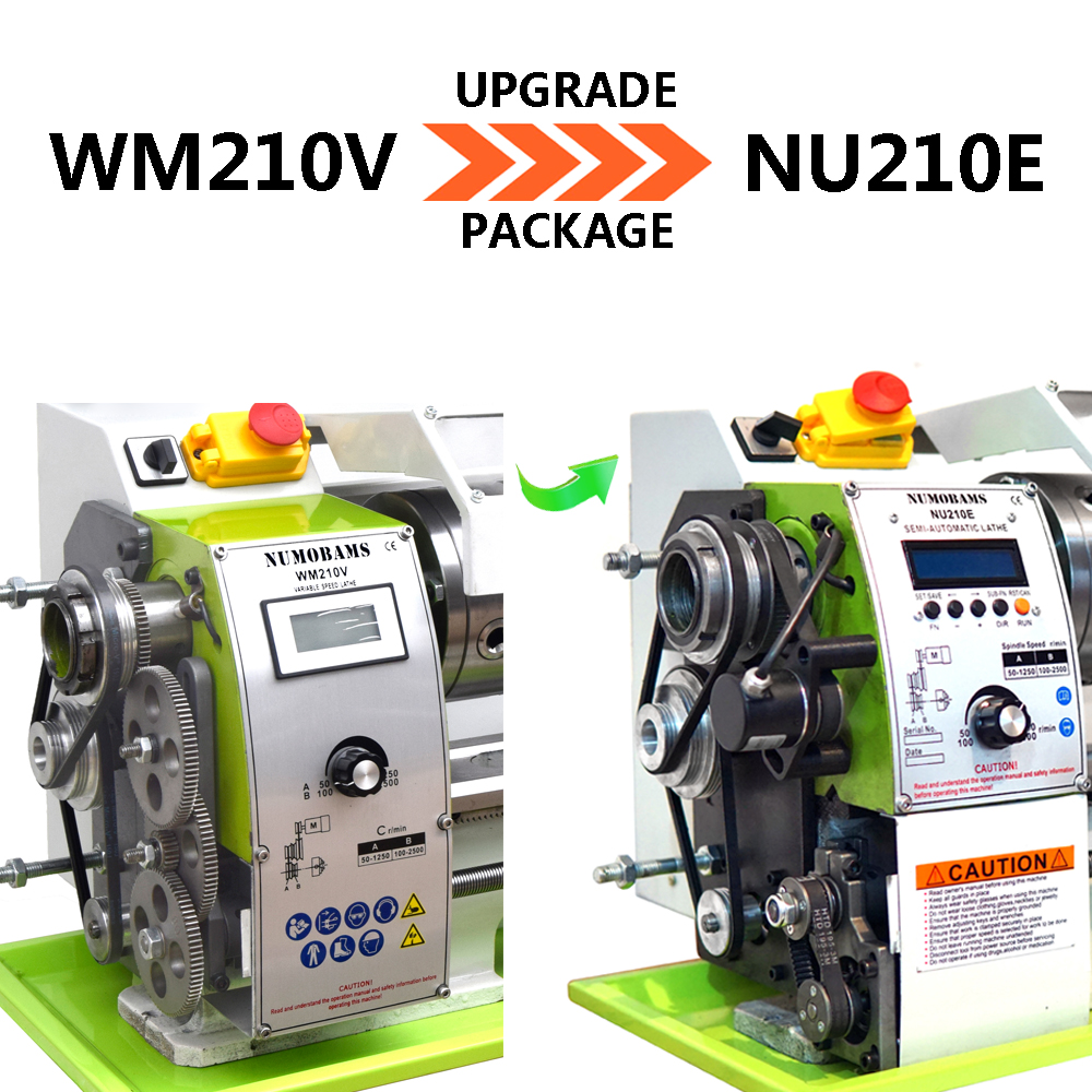
Electronic Lead Screw

Nema 17 motors are used on all of the 3D printers. they are 42mm square and you get the length that gives you the power you want. Because of the huge volumes the steppers are cheap. A 40nm is about $20 delivered. The drivers are also cheap. As the number of micro steps increases the torque goes down. I would suggest a .9 degree/step motor and reducing the number of micro steps. the micro steps do not really do what most people think. The motor if overloaded, will skip steps until it then jumps some number of steps all at once. You have to be careful with current specs. To get the highest speed you need to get a low inductance motor which in turn requires more current per step.
 
To use a wild west analogy, a cowboy can rope a 1000 lb steer and take two wraps around the saddle horn and hold that steer with his hand. The same is true with the lathe. The hand wheel takes advantage of all the frictional losses to amplify its holding power against the stepper motor.

What I did was attach a line to the carriage and the other end over a pulley to a bucket with lead weights. At the time, I didn't have aVSD drive so I ran the spindle at 300 rpm and set the feed rate at 3.5mm/rev or 1050 mm/min. or 41 ipm. Then I kept adding lead to the bucket until the motor stalled. I was able to lift a load of 105 lbs before the motor stalled.

I should note that my drive system goes through the 602 gear box where the torque is doubled by gearing. Also, the 602 has an unpublished feature where the half nut clamping force can be adjusted. As shipped, this feature was not implemented which resulted in the clamping friction reducing the available drive by a sizable fraction.

The Prony brake was actually developed to measure my spindle motor torque. It is far too large to be effectively used on the stepper motor. I measured the torque required to turn the input to the gear box with a torque wrench and with a 3" pulley wrapped with several turns of braided line and a small spring scale. That's how I discovered the effect of the half nut clamping force.
 
Last edited:
Nema 17 motors are used on all of the 3D printers. they are 42mm square and you get the length that gives you the power you want. Because of the huge volumes the steppers are cheap. A 40nm is about $20 delivered. The drivers are also cheap. As the number of micro steps increases the torque goes down. I would suggest a .9 degree/step motor and reducing the number of micro steps. the micro steps do not really do what most people think. The motor if overloaded, will skip steps until it then jumps some number of steps all at once. You have to be careful with current specs. To get the highest speed you need to get a low inductance motor which in turn requires more current per step.
I would agree that many NEMA-17 motors are cheap. I have many on my 3d printer. There are no 40 Nm NEMA-17 motors that I know of, by any reputable suppliers. If you know of such a supplier, please post the URL.

I would, however, believe that those motors are 40Ncm, (not 40Nm,) which is a factor of 100 times less. NEMA motors are made in many sizes, and as a general rule, their size is an indicator of their torque abilities. There are hardly any NEMA-17's being used for full sized CNC, practically speaking, the sizes are NEMA-34 or NEMA-42, which are much larger. This is because the little motors don't put out the required torque. The NEMA sizing XX means the motor measures X.X" on the square face, so a NEMA-42 measures 4.2" x 4.2" on the square mounting face.

The closed loop stepper motor being used is a NEMA-24 with 4 N-m, which is about twice the torque of the original Clough42 ELS motor. 4Nm is about 566 oz-in of torque which sounds like a lot until it is converted to ft-lbs. (~2.97 ft-lbs) The highest torque NEMA-17 I could easily find was 92 oz-in of torque. Not even close to 566 oz-in!

The number of micro steps used is 4. The motor is rated for 5A, and the driver is matched to it. I do agree with your assessment of trying to find a low inductance motor. It's all a trade off between required torque, maximum inductance, current, power supply voltage, and a bunch of other things.
 
I just ordered this kit:

It has what looks to be a very large stepper. If it is the same size stepper you are using then a Nema 17 would be no improvement. I did not realize how much power was required, a factor of 100 is just a bit more.
 
I just ordered this kit:

It has what looks to be a very large stepper. If it is the same size stepper you are using then a Nema 17 would be no improvement. I did not realize how much power was required, a factor of 100 is just a bit more.
Definitely not a NEMA-17. Probably a NEMA-23. Not sure if a NEMA-24 would fit in the cavity.

Looks interesting. Not as nice of a display nor user interface, but it has all the required parts. Let us know how it works. It seems to think it can measure tool displacement in Z. This will have back lash, as it is merely derived from lead screw angle. If you remember to take out the back lash it should work ok. It does not appear to include scales for a DRO, which measure the actual position. Seems to have a decent value though. My ELS integrates the Z and X axis information from the DRO's.

The kit has a manual jog it seems, but I have no idea how 1000 Hz relates to motor speed. mm/sec units would be more helpful. It also seems to be metric units only,don't see a way to select imperial units. I don't know if that ELS can do imperial threads, if that is important to you. I only glanced at it, so maybe I missed that. My ELS implements both metric and imperial threads and feeds. It also displays the DRO's in either system.

The kit does have some features that I like, and may implement on my controller. The only reason I haven't done them yet, is figuring out the data entry issue and the human factors. Since I write my own code, I have to figure that out first. That usually means making little cartoons on what the display should look like for every step of input configuration.

Good luck with it!
 
I haven't read thru the entire post but I assume you watched
where he changed from a stepper to a hybrid servo? In the video he showed how the torque dropped off rapidly with steppers. His final install was with that servo. I have a larger lathe and used a JMC iHSV60-30-40-48 400W integrated servo that has double the torque of the one Clough42 used. I have no trouble making very heavy cuts and no stall. The torque curves on these allow you to use higher speed and utilize the gearbox to increase the torque. I set my PM-1340GT at D-6 which is 6:1 reduction.

The one I used and been working great for > 1 year.
https://www.aliexpress.com/i/2251832779022156.html?gatewayAdapt=4itemAdapt
 
Last edited:
Definitely not a NEMA-17. Probably a NEMA-23. Not sure if a NEMA-24 would fit in the cavity.

Looks interesting. Not as nice of a display nor user interface, but it has all the required parts. Let us know how it works. It seems to think it can measure tool displacement in Z. This will have back lash, as it is merely derived from lead screw angle. If you remember to take out the back lash it should work ok. It does not appear to include scales for a DRO, which measure the actual position. Seems to have a decent value though. My ELS integrates the Z and X axis information from the DRO's.

The kit has a manual jog it seems, but I have no idea how 1000 Hz relates to motor speed. mm/sec units would be more helpful. It also seems to be metric units only,don't see a way to select imperial units. I don't know if that ELS can do imperial threads, if that is important to you. I only glanced at it, so maybe I missed that. My ELS implements both metric and imperial threads and feeds. It also displays the DRO's in either system.

The kit does have some features that I like, and may implement on my controller. The only reason I haven't done them yet, is figuring out the data entry issue and the human factors. Since I write my own code, I have to figure that out first. That usually means making little cartoons on what the display should look like for every step of input configuration.

Good luck with it!
This can do imperial threads according to the video I saw. Like most Chinese stuff there is not enough documentation before purchase for me to really feel comfortable. One interesting thing I saw in the video is that I can specify the length of the thread. Using a stepper makes that possible and allows me to thread closer to the end than I felt comfortable with before.

When it arrives I will scan and post all of the documentation. I figure about a month.
 

Attachments

  • NU210Emannual-a2f8.pdf
    557.1 KB · Views: 4
Last edited:
I haven't read thru the entire post but I assume you watched
where he changed from a stepper to a hybrid servo? In the video he showed how the torque dropped off rapidly with steppers. His final install was with that servo. I have a larger lathe and used a JMC iHSV60-30-40-48 400W integrated servo that has double the torque of the one Clough42 used. I have no trouble making very heavy cuts and no stall. The torque curves on these allow you to use higher speed and utilize the gearbox to increase the torque. I set my PM-1340GT at D-6 which is 6:1 reduction.
I have read that. One can sprinkle more money on the "issue" and fix it. I have a 4Nm stepper and have no issue with cutting on a 10 x 22 class lathe. I have cut 4 TPI threads in steel, which the original lathe has no gears for. The lathe was only set up from the factory for 8 TPI.

At the risk of beating a dead horse, here is my take:

The "issue" is that an attempt is being made to connect the motor through an additional gearbox, and cross feed unit, operating at 32F which is an additional motor load. My original design drove the lead screw directly. It's quite possible that a simple gear reduction could be satisfactory fix, with an appropriate accommodation in software.

As of the moment, the "issue" is sort of a red herring, as it has not been demonstrated that the actual operation of the lathe is compromised. Without a demonstrated lathe operation issue, why fix something that may not be broken?

Making the motor more powerful than the lathe is rated for, is long term asking for trouble. An off shore 10x lathe is never going to have the same capability or rigidity as much larger and heavier machines. The lathes work to some envelope and that's it. Want more? Go to a bigger class machine. You can do more stuff.

My view on the situation is to validate if the motor isn't adequate when being used normally. Holding onto the hand wheel and resisting movement while machining under automated threading or feeding is not normal operation, in my opinion. Don't consider that a safe operation on a normal geared lathe, so what makes it proper for a motorized lead screw? If the motor is not sufficient under normal operation, for conditions that are appropriate to this class lathe, then it is an issue, and there are ways to fix it. (Motors & Gearing choices.)

I would agree that a larger lathe can generate larger loads and could take advantage of bigger, higher torque motors. They also can accommodate larger motors without looking like you strapped a locomotive engine on the side!
 
It is interesting to follow the progress of the ELS. There were a few pioneers who struck out to develop workable systems to eliminate the need for change gears. Clough created a well documented and supported build build series and the rush was on. I, myself jumped on that wagon. A few other adventurous individuals decided to make improvements on some of the shortcoming of the Clough42 system. And now there is a commercially available kit. Given the cost of making change gear sets, I expect that small lathes and the convenience of an ELS, I expect that the lathes of the future will come standard with an ELS.

The above kit is intriguing. Were I looking to buy, I would like to see the specifications before buying. It has no information regarding the size of stepper motor, something that we have discovered is a limiting factor. It apparently does limit the feed rate to .4mm/rev. I would like to see the range of threads available and whether it has both Imperial and metric capability. The manual has no information as to how threading pitches are selected. It could be by selecting a pitch from a library as Clough did or by just by increasing or decreasing the feed rate. If the latter, that is perfectly acceptable for metric threads as they increment by .1mm and having a resolution of .01mm is sufficient. However, Imperial threads don't do well with metric approximations if limited to .01mm resolution.

A fellow named kwackers on github has created a software modification that permits user entry of metric threads in .01mm increments. It is limited to that resolution because of the way that Clough designed the interface. and when I looked at it, there are relatively few Imperial threads that would fit nicely within those parameters. For example, if I wanted to cut a 50 tpi thread for a micrometer, the closest that I could come would be .51mm or 49.80 tpi for a .4% error which would be unacceptable. Adding another decimal place, a .508mm pitch would reduce the error to .0002%.
 
Back
Top