

-
Welcome back Guest! Did you know you can mentor other members here at H-M? If not, please check out our Relaunch of Hobby Machinist Mentoring Program!
You are using an out of date browser. It may not display this or other websites correctly.
You should upgrade or use an alternative browser.
You should upgrade or use an alternative browser.
Erratic behavior from VFD
- Thread starter mikegt4
- Start date
- Joined
- Oct 29, 2012
- Messages
- 1,328
Ah yes, Thank you. I forgot about eddy currents. Actually both are at play. The following article speaks of permeability, but that's just another (inverse) way of saying reluctance.Being picky, the reason is eddy currents, not reluctance. Otherwise you are right. Higher frequencies cause loss unless the motor is designed for that frequency. Same with transformers.
"Explaining Core Losses In AC Electric Motors" https://www.horizontechnology.biz/blog/explaining-core-losses-in-ac-electric-motors?hs_amp=true
- Joined
- Oct 29, 2012
- Messages
- 1,328
Interesting! Thanks for the link, I am glad to finally learn that it is "a thing." Now I really want to try it. I am a little confused about the paragraph at the end where they apply the concept to American motors. They get the 1.74 factor from European mains voltages (400V/230V = 1.74) and then apply 1.74 to 60Hz, resulting in 104Hz. But our mains are 480V/240V, so our factor should be 2.00 not 1.74, unless I'm missing something.I believe I read somewhere that Haas runs their machines that way.
The centrifuge company I worked for ran one of the motors on the machine that way, but used a delta-wye motor wired for 230v and 50 hz (it was a European company) on a 400 volt design feed into the VFD. Instead of typing it out, this article describes how it works.
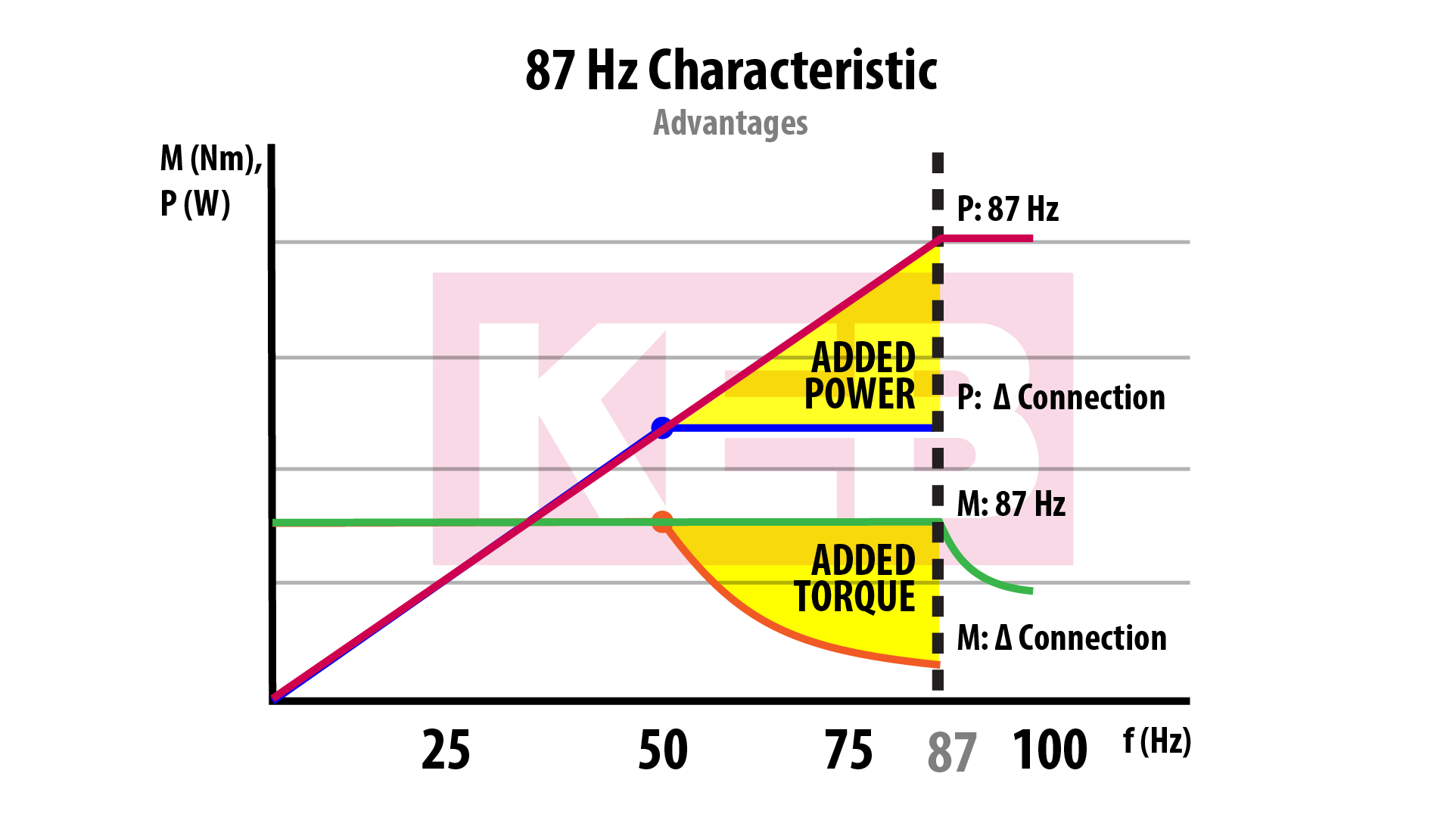
87Hz motor control for Delta Wye VFD operated motors - KEB
This article gives an overview of the 87hz motor operation for delta/wye motors. The trick allows a motor to be oversped while keeping the torque constant. Effectively increasing the available motor power.www.kebamerica.com
- Joined
- Jun 12, 2014
- Messages
- 4,812
It is 2.0 (120Hz) for US motors with a base speed of 60 Hz. A previous similar discussion and real world application in the link. Just not practical in the hobbyist setting. Evidently cooling is not an issue, which was a concern I had and the motor needs to be capable of sustained higher speeds so I am figuring this is more applicable to inverter/vector motors which maintain full Hp up to their maximum speed of around 5-6K for motors 10Hp and under. In this case I still feel the 4 pole setting is the practical, one rarely is pushing the motor at maximum output for any period of time and one would be using smaller endmills at speed. It is more a matter of keeping it simple in my book, performance wise I do not feel it would be noticeable.
Encoder requirements for new VFD system
Rebuilding P&W twin spindle gun drill and the next step is to replace the ancient spindle drive motors and the change pulley setup with dual VFD's. Since these are basically spindle drives, I'd like the most precise RPM control. I know it is only drilling, but we are just talking about...
www.practicalmachinist.com
They are referring to a delta-wye motor, the 1.74 ratio is the same between the wye and delta windings with a 50hz or 60hz motor, so in the US with our 60hz frequency, the motor would be 277/460v instead of 230/400v on 50hz. With that kind of motor, you would need to program the VFD with a motor base voltage and frequency of 277/60hz and that would give you the maximum frequency of 104hz at 480v. If you used a 230v motor with a rated 60hz frequency, then you could run that up to 120hz, but you can’t do that with a delta-wye motor without overspeeding it.Interesting! Thanks for the link, I am glad to finally learn that it is "a thing." Now I really want to try it. I am a little confused about the paragraph at the end where they apply the concept to American motors. They get the 1.74 factor from European mains voltages (400V/230V = 1.74) and then apply 1.74 to 60Hz, resulting in 104Hz. But our mains are 480V/240V, so our factor should be 2.00 not 1.74, unless I'm missing something.
- Joined
- Oct 29, 2012
- Messages
- 1,328
Thank you, you revealed a blind spot in my knowledge and prompted me to go illuminate it. The crucial thing I never realized is that America is unique in having two different 3-phase supply voltages (or, "many," if you want to count all the variations on "low" voltage 3-ph). I was aware of the sqrt(3) factor between wye and delta but it never occurred to me to question why I've never needed to permanently wire an American motor for a "low" voltage of 138V, or a "high" voltage of 277V (apart from wye/delta start) despite 12-wire motors availing those options. Meanwhile working on European equipment I do have to choose 230V or 400V. Europe (broad brush, I know) only has one 3-ph supply voltage. So, back to the point, they don't have the option for anything over 1.74x.They are referring to a delta-wye motor, the 1.74 ratio is the same between the wye and delta windings with a 50hz or 60hz motor, so in the US with our 60hz frequency, the motor would be 277/460v instead of 230/400v on 50hz. With that kind of motor, you would need to program the VFD with a motor base voltage and frequency of 277/60hz and that would give you the maximum frequency of 104hz at 480v. If you used a 230v motor with a rated 60hz frequency, then you could run that up to 120hz, but you can’t do that with a delta-wye motor without overspeeding it.
Last edited:
Update, I took the drum switch apart and cleaned the contacts, no change. I did some milling today, as usual the motor acted up for 2 tries than ran flawlessly. When the motor acts up the VFD makes a bit of a hum and I immediately return the lever to N and wait for the hum to stop (a second or two) before moving the lever back to F, usually the motor will then go forward normally and will continue to operate normally. The motor has never acted up when the drum switch is turned to R.
Drum switch only supplies a signal (F-N-R) to the VFD which is wired directly to the motor. Wired per instructions. Motor is a GE 1hp, 1150 rpm, 220-440 3 phase, it is listed in the Millrite spec sheet at 1200 rpm with spindle speeds of 250, 430, 725, 1160, 2300, 3400 which matches the spindle speed tag on my machine.
Drum switch only supplies a signal (F-N-R) to the VFD which is wired directly to the motor. Wired per instructions. Motor is a GE 1hp, 1150 rpm, 220-440 3 phase, it is listed in the Millrite spec sheet at 1200 rpm with spindle speeds of 250, 430, 725, 1160, 2300, 3400 which matches the spindle speed tag on my machine.
- Joined
- Oct 29, 2012
- Messages
- 1,328
Ok then you need to compare the 220V (and 50Hz?) To the parameters that are entered in the drive.Update, I took the drum switch apart and cleaned the contacts, no change. I did some milling today, as usual the motor acted up for 2 tries than ran flawlessly. When the motor acts up the VFD makes a bit of a hum and I immediately return the lever to N and wait for the hum to stop (a second or two) before moving the lever back to F, usually the motor will then go forward normally and will continue to operate normally. The motor has never acted up when the drum switch is turned to R.
Drum switch only supplies a signal (F-N-R) to the VFD which is wired directly to the motor. Wired per instructions. Motor is a GE 1hp, 1150 rpm, 220-440 3 phase, it is listed in the Millrite spec sheet at 1200 rpm with spindle speeds of 250, 430, 725, 1160, 2300, 3400 which matches the spindle speed tag on my machine.
- Joined
- Jun 12, 2014
- Messages
- 4,812
Not 50 Hz motor, I would post a picture of your motor name plate information. If it is a 1150 RPM motor then it would be a 6 pole. so maybe you entered the wrong motor data. Other things to check would be the speed pots can get flakey, and I still would not use a used drum switch even with the contacts cleaned. The VFD low voltage inputs are a few mA. Recheck all your connection to the VFD that everything is tight.
I started using my Millrite by using the drum switch wired to the VFD until I built a control pendant for it, I agree with Mark that it is not a good long term solution for starting and stopping for low current control circuits, it was designed for motor rated current. Another problem you have by using the drum switch is if you trip the VFD or have a power failure, the mill will start running when it regains power unless you remember to turn the switch to the off position.
You can build a pendant that you can move to where it is needed, or mount a control box with start/stop buttons and a switch for reverse. You would program your VFD for the three wire control method, works great and is much safer with an interruption of power.
It still sounds like a programming issue, or possibly a wiring issue with the motor. Check and make sure you are actually on the 230v connections and not 460v, as well as all the wire connections are tight and the wires are making contact properly. It’s strange that it works in one direction and not the other, but electrical problems can be weird that way.