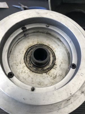
First cut from my 8520...what is this god awful noise coming from...

Now that you have the top clip off, press the sleeve out through the pulley from the top. It should push the bottom bearing out with it. Impossible to say how much trouble the bearings will give you. Sometimes the bearings just fall out/off (a good or bad thing depending on your point of view). The top bearing in the rear cone pulley on mine was wallowed out several thousandths, and had to be sleeved and re-bored. I also sleeved and re-bored the brake ring contact surface in the front cone pulley. The end result was a very quiet machine and a brake that locks things up with just a little pressure on the lever.

I recommend replacing all of the bearings while you have it apart. They're standard sizes, and inexpensive. The only ones that I re-used were the thrust bearing on the knee screw and the quill bearings (but I have spares anyway).

-Jon

Thanks Jon. Any idea on the broken piece of the sleeve still stuck in the plate? Is that part of the plate or can the remaining broken piece be pressed out? Also, why does the piece have to be brazed on? Seems like it can be welded back together just as easily with more strength. Is it a balance issue?
 
Thanks Jon. Any idea on the broken piece of the sleeve still stuck in the plate? Is that part of the plate or can the remaining broken piece be pressed out? Also, why does the piece have to be brazed on? Seems like it can be welded back together just as easily with more strength. Is it a balance issue?

Sorry to confuse you. I see now that your sleeve appears to be tubing pressed into the flange. Mine is turned from one piece. Not knowing how it's retained (that looks suspiciously like JB-Weld around the edge), you will probably have to bore it out. Making the replacement will be good practice fitting bearings to a shaft and cutting snap ring grooves. Press it back in with LocTite 480 (or pretty much any LocTite, for that matter) and it ain't ever coming back out. Ideally, you should do the final turning on the entire assembly. If I were you I would decrease the ID as much as the quill will allow to make it less likely to break again.

-Jon

Thanks again Jon. Sadly, I won't be boring anything out with my mill out of commission. I have a buddy that owns a machine / welding shop and so I'll just pass this project on to him. I'm out all next week on vacation so I'll update my progress when I return...thanks again!
 
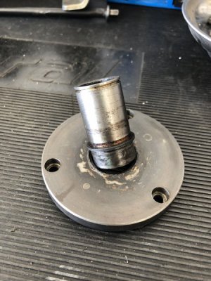
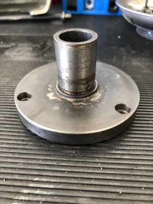
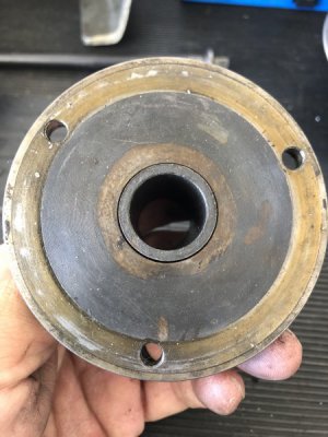
Got the sleeve off. I've attached a couple of pictures. It obviously looks to have been replaced at some point. Whoever replaced it used thicker rod as the inside diameter is just about as wide as the spindle shaft. I still don't understand why I can't just weld this back onto the plate? That should hold pretty well. Is it a balance issue?

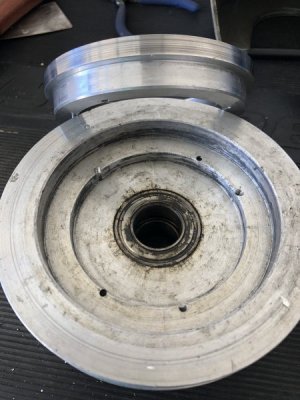
Also, take a look at the bottom of my pulley. It appears as though the brake plate was replaced by a custom-made aluminum piece that was then pinned to the pulley and screwed in. Can someone confirm? Seems weird that they would do that...

Also, the top bearing on my pulley needs to be replaced. I'll end up replacing both. Is there some kind of part number / link online for these?

Photo Jun 25, 1 54 14 PM.jpg

Photo Jun 25, 2 15 53 PM.jpg

Photo Jun 25, 2 16 01 PM.jpg

Photo Jun 25, 2 17 06 PM.jpg

Photo Jun 25, 2 20 20 PM.jpg
 
Last edited:
What, you
Got the sleeve off. I've attached a couple of pictures. It obviously looks to have been replaced at some point. Whoever replaced it used thicker rod as the inside diameter is just about as wide as the spindle shaft. I still don't understand why I can't just weld this back onto the plate? That should hold pretty well. Is it a balance issue?

Also, take a look at the bottom of my pulley. It appears as though the brake plate was replaced by a custom-made aluminum piece that was then pinned to the pulley and screwed in. Can someone confirm? Seems weird that they would do that...

Also, the top bearing on my pulley needs to be replaced. I'll end up replacing both. Is there some kind of part number / link online for these?

You have an interesting challenge here. I meant to mention the screws and pins and obvious wear, but I didn't realize that it was a separate assembly entirely. Once the sleeve broke it ran a long time with that inside surface rubbing.

It's looking to me like the previous owner removed the brake plate/ring (8520-10 in the exploded diagram) and set it up so that the tab on the brake lever would wedge against the outer surface of the new piece added to the pulley, which is why it was pinned to resist the torque. The brake lever normally sticks straight out from the side of the pulley guard, and I remember thinking it was at a weird angle in your earlier video. Could you take a picture of the whole collection of parts?

In your earlier video it looked like the pulley sleeve flange was much thicker. Was there a spacer under the pulley sleeve that we're not seeing here?

I think that I would turn a new sleeve from 4130 tubing, make it a light press fit, and "glue" it in with LocTite. I would still try to beef up the wall thickness if there's any clearance.

-Jon
 
What, you


You have an interesting challenge here. I meant to mention the screws and pins and obvious wear, but I didn't realize that it was a separate assembly entirely. Once the sleeve broke it ran a long time with that inside surface rubbing.

It's looking to me like the previous owner removed the brake plate/ring (8520-10 in the exploded diagram) and set it up so that the tab on the brake lever would wedge against the outer surface of the new piece added to the pulley, which is why it was pinned to resist the torque. The brake lever normally sticks straight out from the side of the pulley guard, and I remember thinking it was at a weird angle in your earlier video. Could you take a picture of the whole collection of parts?

In your earlier video it looked like the pulley sleeve flange was much thicker. Was there a spacer under the pulley sleeve that we're not seeing here?

I think that I would turn a new sleeve from 4130 tubing, make it a light press fit, and "glue" it in with LocTite. I would still try to beef up the wall thickness if there's any clearance.

-Jon

Yeah that's exactly what it looks like Jon. Seems odd to me that the brake lever was so critical to the owner of this machine that they decided to trash the original brake plate and completely fabricate a new piece that would mount onto the pulley. The original brake plate is now gone and the original pulley was permanently modified to accommodate this new piece. What a waste. I would have just remove the brake handle...I don't feel like it's that important....you can't wait an additional 3-4 seconds for the motor to stop?

The brake handle was modified too. They riveted a small piece of leather that then makes contact with the outer surface of this plate to bring the machine to a stop. I have to admit...it works...but I would never permanently alter this machine this way just for a brake.

There is no spacer in between the pulley sleeve flange and the head. Just the pulley sleeve flange.

I'll take your advice on the new sleeve. The ID of the sleeve is just about as thick as the spindle shaft so there's no making it any thicker. Personally, it seems thick enough to me already. You can see there's a lip on the sleeve tubing. That lip rests against the shoulder of the inner ring of the flange. I'm thinking perhaps it would be best to bore out the flange a little wider and just make the tubing thicker?

Zak

Aha! It's all starting to make sense now. That's actually kind of clever.

You need some kind of brake in order to tighten the draw bar. I suppose you could use a pin spanner that fit into the sockets of the cap screws in the top plate, or the dowel pin holes if they're below the surface. Or drill two more holes. But then you need two tools to tighten it up.

Whatever material you start with, when you turn it down to fit the bearings leave as much radius at the transition as you can to minimize the stress riser. The sharp inside corner is why it broke.

So you need to decide whether to keep the existing setup or fabricate a new brake ring, which is ductile iron. Like I mentioned, I had to silver braze the two pieces of mine back together. I'm sure it broke on yours too, but the previous owner came up with a different scheme. I think they all break eventually because Clausing made a flexure opposite the brake handle by drilling a small hole and opening a slot on the inside edge. Another stress riser caused by too small a radius. It would have been much better to mill a 1/4" (or larger) radius bite out of the ring. Or two. Or three or four. If you decide to go that route and do away with your extra pulley piece, I might be persuaded to do a drawing.

-Jon
 
Last edited:
Aha! It's all starting to make sense now. That's actually kind of clever.

You need some kind of brake in order to tighten the draw bar. I suppose you could use a pin spanner that fit into the sockets of the cap screws in the top plate, or the dowel pin holes if they're below the surface. Or drill two more holes. But then you need two tools to tighten it up.

Whatever material you start with, when you turn it down to fit the bearings leave as much radius at the transition as you can to minimize the stress riser. The sharp inside corner is why it broke.

So you need to decide whether to keep the existing setup or fabricate a new brake ring, which is ductile iron. Like I mentioned, I had to silver braze the two pieces of mine back together. I'm sure it broke on yours too, but the previous owner came up with a different scheme. I think they all break eventually because Clausing made a flexure opposite the brake handle by drilling a small hole and opening a slot on the inside edge. Another stress riser caused by too small a radius. It would have been much better to mill a 1/4" (or larger) radius bite out of the ring. Or two. Or three or four. If you decide to go that route and do away with your extra pulley piece, I might be persuaded to do a drawing.

-Jon

I didn't think about needing the brake to hold and tighten the draw bar. I guess I didn't think about it because I'm using a collet holder that has two straight edges on both sides. I use a small adjustable wrench on the top of the draw bar and a crescent wrench on the collet holder to tighten. I guess I would have figured it out really quick if I ever put in standard collets or a chuck.

So I took the collar and plate over to my buddies shop and he recommended a different solution on the plate. He's going to reduce the diameter of the bottom of the collar where it meets the bottom of the plate and do a filler weld around the bottom of the plate...fusing it to the inside ring of the plate. He's then going to face both sides of the plate on his lathe to knock off those sharp corners on the inside hole of the top of the plate and any extra slag on the bottom of the plate. He's confident it will hold for many years. I drew up a quick and crude picture of the plan. Red representing weld around the circumference of the color/inner ring.

plate.png
 
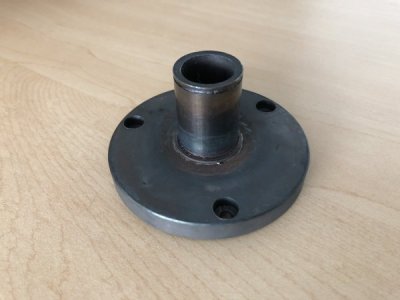
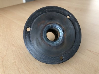
I have the plate done. I've attached some before and after images. I just need to file down some of the welding slag but other than that, happy with the way it turned out. Not original looking by any means but at least it's completely hidden from view and I don't think the collar will be breaking off any time soon. Ordered some new bearings for the pulley and then will reassemble.

flange1.jpg

flange2.jpg

flange3.jpg
 
Back
Top