- Joined
- Dec 18, 2019
- Messages
- 6,464
Looking at the backlog of projects, decided to do this one next. This design is copied from @RJSakowski. Looks like:
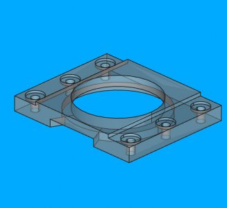
With RJ's permission (a while ago) I posted the FreeCAD file in Downloads. So if you want the file, download it from there.
Started out with a piece of 1x4 A36 steel. Took awhile to whittle it down to the requisite 5/8" thickness.
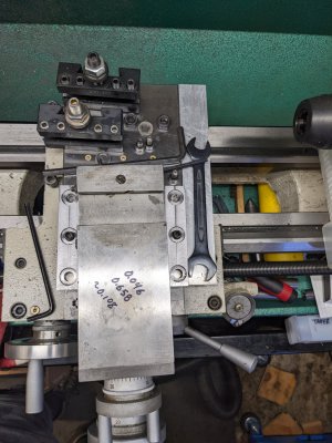
Finally got it to the point of cutting the edges down. Used a roughing mill in two passes for the left side and got a little braver and tried a single pass to remove 0.115". Replaced the rougher with a finish carbide mill and did the last 0.010".
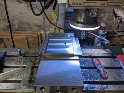
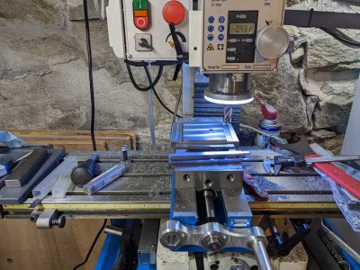
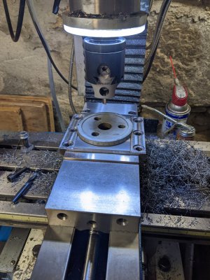
Put in the counter-bores with a 5/8" end mill. Drawing called for 0.600", but I had 0.625", close enough for this. I also drilled the bolt holes to M8 clearance, since I have M8 studs in the lathe now. Might as well do the other ones with M8 as well.
Got to the point of doing the central hole. Err, how am I going to do that. Remembered I had a few hole saws and picked out a 2" hole saw. Set it up in the mill and turned it on slowly. Holy cow, talk about run out! About 1/8" run out. Fortunately the required hole is a bit larger, so decided to still use it. Used a ton of cutting oil and had to clear out the swarf a lot. Eventually punched all the way through.
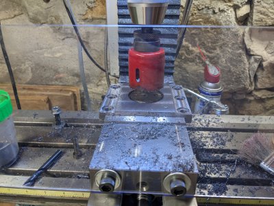
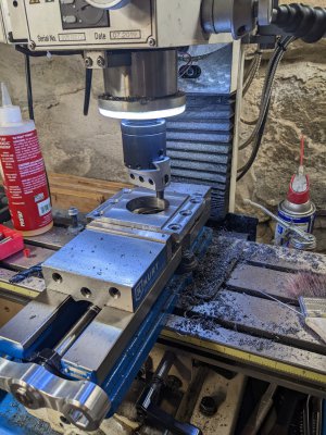
To enlarge the hole I was going to use the boring head on the mill. I set everything up and stared at the hole. Arggh, something isn't centered. Did a clean up pass on the boring head and decided to take it off the mill for figuring out what went wrong. Have to confirm this, but it seems to be off by about 1mm in X. I don't know how this happened, I used the 1/2 function in the DRO when setting up the piece.
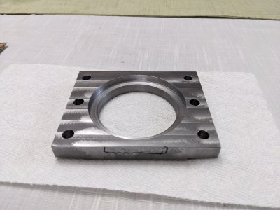
Anyways, I cleaned it up and deburred stuff. It fits fine on the lathe so far. I just think the main hole is off center in X. Will reindicate it and bore out the hole. It is currently at about 53mm, and needs to be 70.38mm in diameter. So there is enough wiggle room to fix it.

With RJ's permission (a while ago) I posted the FreeCAD file in Downloads. So if you want the file, download it from there.
Started out with a piece of 1x4 A36 steel. Took awhile to whittle it down to the requisite 5/8" thickness.
Finally got it to the point of cutting the edges down. Used a roughing mill in two passes for the left side and got a little braver and tried a single pass to remove 0.115". Replaced the rougher with a finish carbide mill and did the last 0.010".


Put in the counter-bores with a 5/8" end mill. Drawing called for 0.600", but I had 0.625", close enough for this. I also drilled the bolt holes to M8 clearance, since I have M8 studs in the lathe now. Might as well do the other ones with M8 as well.
Got to the point of doing the central hole. Err, how am I going to do that. Remembered I had a few hole saws and picked out a 2" hole saw. Set it up in the mill and turned it on slowly. Holy cow, talk about run out! About 1/8" run out. Fortunately the required hole is a bit larger, so decided to still use it. Used a ton of cutting oil and had to clear out the swarf a lot. Eventually punched all the way through.

To enlarge the hole I was going to use the boring head on the mill. I set everything up and stared at the hole. Arggh, something isn't centered. Did a clean up pass on the boring head and decided to take it off the mill for figuring out what went wrong. Have to confirm this, but it seems to be off by about 1mm in X. I don't know how this happened, I used the 1/2 function in the DRO when setting up the piece.
Anyways, I cleaned it up and deburred stuff. It fits fine on the lathe so far. I just think the main hole is off center in X. Will reindicate it and bore out the hole. It is currently at about 53mm, and needs to be 70.38mm in diameter. So there is enough wiggle room to fix it.


