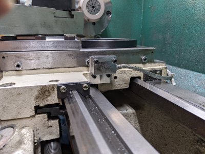
G0602/G0752Z Compound Clamp

So 6 M6 screws? There are 3 M6 screws now. Not hard to do, but why not up size the existing M6 to M8?
The short answer is that I had the screws at hand. I did not investigate whether going to an M8 would create any problems due to the lrger size of the cap.
 
The short answer is that I had the screws at hand. I did not investigate whether going to an M8 would create any problems due to the lrger size of the cap.
I'll check if the 2mm extra cap height can be accommodated.

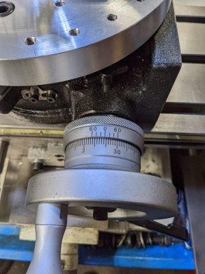
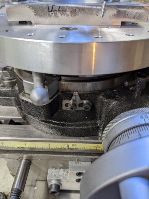
Finally got the piece bolted to the fixture plate. Not too hard. Had to stop for a geometry break to figure out how to get the mouse hole to come out ok. Having no experience at this certainly slowed me down. No CNC here with magic functions to help. Think I have it figured out. Surprised that I had a tough time reading the rotary table. Think the angle in the picture is 185 d 40' 40".
PXL_20220715_170558962.jpgPXL_20220715_170609201.jpg
So according to the design I need to move the table +/- 25 degrees from this setting and also move the tool +/- the tool radius inward in X from zero. Then I simply make a cut on the Y axis.
 
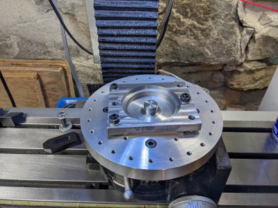
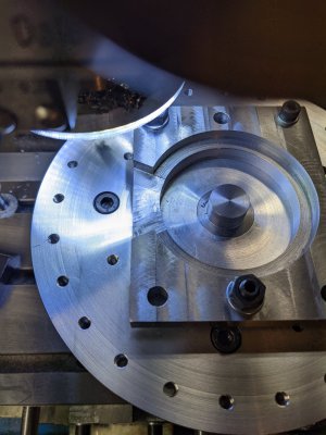
Learned some more today about using the rotary table, and my mill. Discovered all about not having enough Y travel to do the job. So, I rotated the table by 90 degrees, so the cut was in the X axis. I used the protractor wheel as a centering device around the mandrel pin I made. Then lifted out the protractor to keep it from being machined. Here is the piece bolted to the table.
PXL_20220715_161650148.jpg
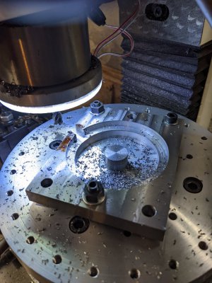
The first cut. Hope I got the angle right! Seems I went a little too deep. Used a 3/8" 0.020" radiused carbide end mill at 2500 RPM.
PXL_20220715_191023104.jpg
And the finished cut.
PXL_20220715_193343636.jpg
Ran out of time to take pictures, but have the lathe cross-slide up in the mill and have been drilling and tapping the mounting holes. Using M8 threads. I drilled and tapped 3 out of the 4 holes and had to stop. Will pick this up later this weekend.

I looked into using M8 screws to hold the protractor in place. There isn't enough room for the standard cap height. So will go with 3 additional M6 screws. Looking at this design vs the original, wow, what a difference. The original is, well, flimsy looking.
 
Here's the last screw hole being fitted. It's sitting on the mill. Last one on the back left. (Top right in the picture.) Kind of an awkward spot, but got it to work.
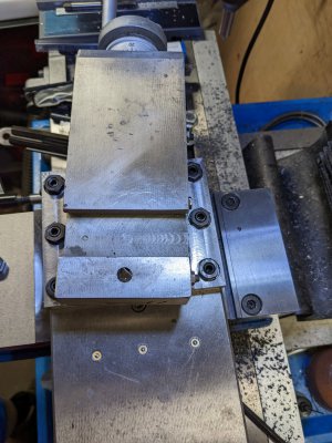
PXL_20220716_151444096.jpg
A fit check on the lathe revealed that while there was clearance for the studs and nuts, there wasn't quite enough room for the wrench! The M8 nuts that I had were 13mm across the flats, and my 13mm wrench is a little taller than the supplied Grizzly 14mm wrench. So back to the mill to make the sides thinner by 0.75mm. Used a 1/2" carbide end mill with 0.060 radius.
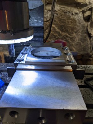
PXL_20220716_161935976.jpg
There's nearly 12mm thickness on the flange, so it will be fine. (Flange thickness original: 12.7mm, new: 11.95mm)
Final check that the wrench has clearance on all 6 locations. Pretty happy with how it came out, despite my rookie mistakes.
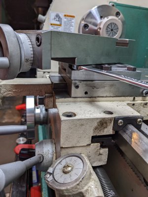
PXL_20220716_164127894.jpg
What's left to do? Adding the extra 3 M6 screws for the protractor hold down, and reinstalling everything again, including the cross-slide DRO.

Also needed is to fix the poor alignment of the cross slide DRO head to the mag tape. Need to make a taper piece (or something else) to fix the tilt. The read head is tilted 4-5 degrees with respect to the ways. This is because the mount is attached to the saddle which is cast. It is about 4 degrees or so from vertical. What is there is pretty ad hoc, difficult to adjust and does not address the alignment issue. What I'd like is something with locking adjustment. Probably think about it today and see if I can implement it.
 
that's really impressive, well done! It'll be interesting to hear what you think once you get to use it some.
 
Been looking for a way to make the bracket. Think I will make a simple part first to see if it is close enough. Really can't make an adjuster on top of the sensor, because the chip shield and mag tape are above the sensor. Below the sensor might be possible, although there is only about 15 mm available. Might be touchy that way. Think I will just make a simple rectangular block of aluminum with a taper and adjust as necessary. Only needs to be 3/8" thick or so, and 1.2" x 1.5".
 
that's really impressive, well done! It'll be interesting to hear what you think once you get to use it some.
So far I can tell it bolts down really tight, can't feel any giving, like the original did. It is solid. Haven't done the 3 extra M6's yet. Will have to practice bolt circles first on a scrap.
 
I cut the heads if my hex head screws down and ground an open end wrench down to fit between the cross slide and the clamp. The clamp actually bends the cross slide slightly, as evidenced bya change in gib clearance. I adjusted my gib with the clamp tightened.
 
I had M8 x 30mm set screws, so I used them, along with some grade 12.9 M8 nuts. I had no clearance problems with the nut, just with the wrench, which was thicker than the original Grizzly wrench. The nuts I had were 13mm, so the Grizzly wrench didn't fit.

I thought about grinding a wrench to fit and decided against it. Didn't want a special wrench for the lathe, since I figured I'd misplace the darn wrench in under 15 minutes! I only needed a little bit of extra clearance and decided just to mill just enough to get it so my thickest wrench would work. The setup on the mill took seconds and the machining was done in a minute. For me, it was the right choice.

The M8's really snug down the clamp. It doesn't take much tightening to immobilize the compound. It's apparent that the M6 screws on the wheel are the weak link.
 
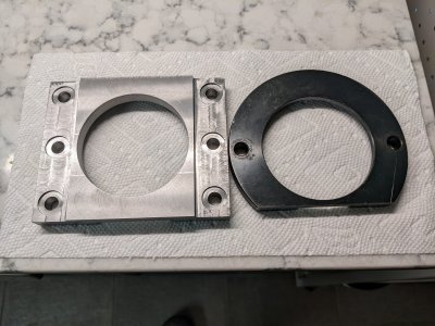
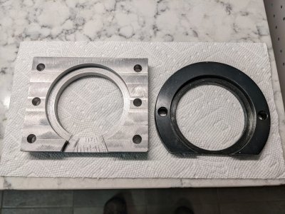
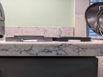
Since I didn't show this before, this is the difference between the old and new clamp.
PXL_20220717_204413785.jpg
Top view.

PXL_20220717_204353701.jpg
Bottom view.

PXL_20220717_204441185.jpg
Side view. The old one would noticeably flex. The new one seems pretty solid on the lathe.

Finished the cross-slide DRO mounting. Here's a picture of that.
PXL_20220717_200626569.jpg
The bottom half of the aluminum plate is cut with a 4 degree taper to compensate for the casting angle. This makes the bracket vertical face vertical. Next is back to the additional M6 screw installation. That will be tomorrow's task.
 
Back
Top