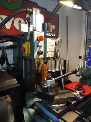
G0773 Lathe / Mill Combo

Don't know if this is related to your motor problem, but ...
The motor on one of my bench grinders went "unstart" on me a month or so ago, but I was able to get it to run by spinning up by hand. Opened it up, checked the start switch contacts and capacitor ... no problem. Reassembled, no start. I finally figured out that the rotating part of the start switch had slid sideways on the shaft a bit, preventing it from closing the switch. Loosened the setscrew, moved the switch over, tightened the setscrew, and all is now well.
 
HMAN, This is definitely food for thought & I thank you for your input. Mine has a horseshoe affair, with the start contact in the middle of the curve, mounted inside the end cover. The centripical spring pack has a plastic ring that either rides against the contact in the run position to force the contact open or springs back. Perhaps it has shifted on the shaft? This is going on my to do list next time I have to get back to that area.

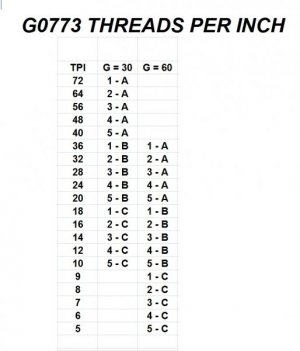
As for now it is working! I'm needing an 11 TPI for a part I'm making - seems everything on my mill is 5/8 - 11.

I'm about to do the math & make some changes. Here is what's available.

TPI AVAILABLE.jpg

You can be sure my next lathe with include 11, 13 & a host more TPI selections.
 
Just for fun, I tried playing with the probable gear ratios that might produce a threading table like you have. Couldn't figger out any "G" gear that would get you to either 11 or 13. MAYBE you could swap some other gear for one of the 1,2,3,4,5 or A,B,C gears. But as far as I can tell, playing with G just won't do it.

On the other hand, I think there's a way for you to get 27 TPI (which some members have posted about not being able to get on their lathes). It would require a 40 tooth G gear, and setting 1-B.
 
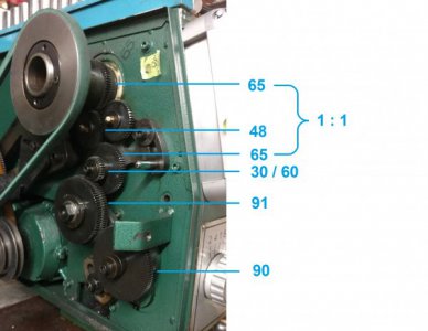
Thanks hman! I played with the chart more today EDIT: 07/02/2019. hman shows the math a little further down. My attempt at playing with ratios was off. So this is just the open gear section without an incorrect chart.

THREADING GEARS.jpg


I'm about to go slap the 35 onto the G spot, set the dials to 4 - C & check my math. Update by 2300.
 
Last edited:
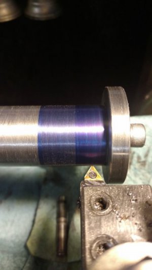
1st run.

THREADING 20190701 01.jpg

My thread gauge only goes to 40. Forgot to change the dials. Should be 66 TPI.

OK. Set the dials.

THREADING 20190701 03.jpg

That is off a bit.

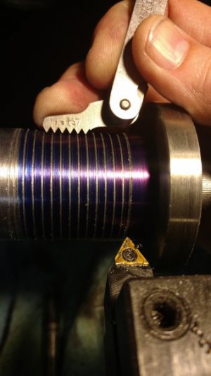
THREADING 20190701 04.jpg

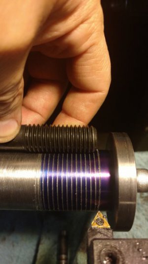
5/8 - 11 stud matches the thread gauge - but still shows this is off a fractional bit over the course of an inch. The disk on the right side of the test subject is what I need to be 11 TPI. I think I'll venture it. Unless $7 - $10K appears as an unexpected blessing......... I'll see if this will get me there or cut my diameter to fit inside the threads, thus clearing them altogether.

I think this is a case of [my math was wrong]. The difference actually does stack up to cause an ever expanding error as length increases. When is 3 3rds not a whole? 0.333 / 0.666 / 0.999....................... As much as I wanted to truly understand this, I simply could not move this beyond simple ratios.

In conclusion: My chart is plain wrong, but hman straightens it all out below!
 
Last edited:
Unfortunately, I have no way of knowing the gear sizes (tooth counts) represented by A,B,C or 1,2,3,4,5. The way I approached the problem was to use the formula: Combo/G=TPI. For instance, using the second-to-last line of your chart, 4C/30=12TPI leads to 4C=360. Checking, 4C/60=360/6=6TPI. That works. Now plugging in G=25 and G=35, I would predict 14.4 and 10.29 TPI, respectively ... NOT the 13 and 11 you were hoping for.

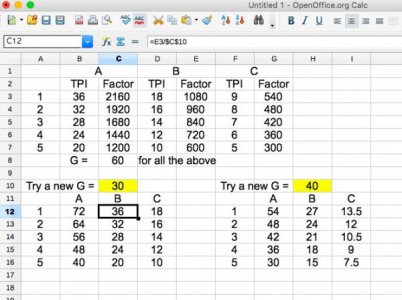
Just for fun, I worked up a quick spreadsheet (using Open Office, not XL - don't have XL on my Mac). The upper half calculates the "fudge factors" of all the 12345ABC combinations, based on your TPI original table and G=60. The lower half calculates the result of changing G. I've included two such tables. The one for G=30 is intended to check the math. It correlates with the G=30 settings on your original table, so I'll claim that my math is correct. The one to the right sets G=40, and you can see where I got 27 TPI for 1B.

I don't know how successfully I can reformat the spreadsheet for XL. Open Office can supposedly do that, so if you want me to try, send me a PM.

Gear chart Open Office.jpg
 
hman I thank you for taking the time to show me the right approach to this! I'll have fun doing the math.

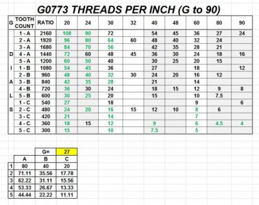
So I made a spread sheet that would do the math & played with the 'G' gear tooth count.

CUSTOM G GEAR RESULTS.jpg

Assuming a smaller gear than the stock 30T could fit, I see some benefits to making these gears. But as hman stated, nothing gets an 11 TPI with just the 1 gear change.
 
Last edited:
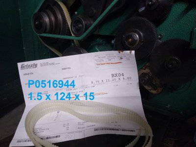
Well, I did it. I wore out the timing belt that goes between the motor & idler puller. Grizzly doesn't offer the belt listed in my parts list & the local supply house couldn't match it either. So, I went about my search on google & found 1 from Grizzly. Grizzly has completely retired from servicing my lathe - but carries what I needed under a new part no for a different machine. I bought 4!!!
 
Oops, forgot to include the pics & info. TIMING BELT 01.jpg

20191024 TIMING BELT.jpg

I have since learned that part of my problem with tearing up the timing belt was over tightening the other belt. it couldn't slip any more. Never mind it just jumps off otherwise. Always something to bring out the 'engineer' waiting to be designed out of these things.
 
Some might remember this has the BX QCTP installed (retrofitted). It's always different from the intended design with this model as the mount is simply a post (stud) as opposed to the usual wide T slot. So, I turned the end of the new post down & threaded it & away we go! Recently, I lost the ability to loosen the top nut for angle adjustments. The whole thing moved. So, once the part I was working on was complete, it was time to get to the bottom of this. I pulled the set screw out of the cross slide with the intention of drilling an indent in the stud. Not happening. Long story short: Clock the stud & mill a flat into it! I went up a size for the set screw while I was at it! Not gonna be a problem any more!

Also, I made a holder for a - not sure what to call it. When loosening the drawbar on the mill portion a rod is needed to insert into a hole in the side of the spindle to counteract the loosening. I'm using a steering wheel tilt stalk because it's longer & more comfortable. The holder is from scrap.

20191028 01.jpg
 
Back
Top