- Joined
- Feb 1, 2015
- Messages
- 9,605
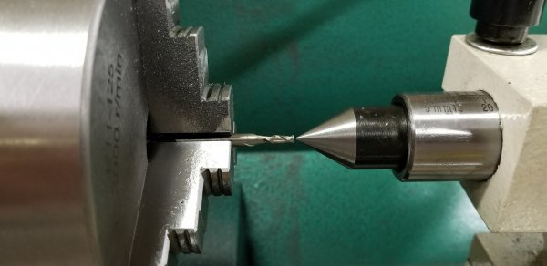
I mostly use 1/8" to 3/8" HSS tool bits with my 602. There is far less grinding involved with the smaller tools and the increase in rigidity is lost on a small lathe like the 602. However, my insert tooling has 12mm shanks.
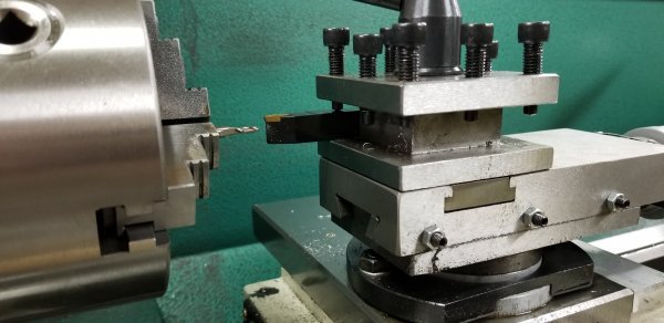
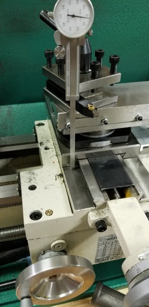
The modification of the compound was one of my first on the 602 and I highly recommend it. I designed a 6 bolt clamp for mine. https://www.hobby-machinist.com/threads/improved-g0602-compound-clamp.34796/
A commercial kit is available based on that design. I believe that Peter Belfanti is the manufacturer.
Peter Belfanti
Belfanti Machine Works
www.belfantimachineworks.com