Group Project: Dividing Head - The Build

It looks good.

With the smaller DIa is the center to center distance still going to work?

I can not tell from the pics, Is there any relief or rake or clearance behind the cutting edges of the hob?
 
Flyingfool! Thanks for checking in.
The center line distance between the worm and the gear is about 2.1". The plans call for 2.028". So its about 72 thou too far apart. I can probably cut deeper teeth if this is necessary but the shifter has about 180 thou of adjustment so I hope that will compensate? We may need to assemble one and test it.
There is about 5 deg of rake and 5 deg of relief on the central 3 cutting teeth. I changed the tooth configuration after the first gear. I am considering buying a 1-4 tap and using that as a hob. I think that will work well from what I am seeing. The initial guidance cuts in the gear are critical so the tool I made earlier has been helpful.
 
Who was doing the trunnion? Maybe we can save this.

That would be me.

Been through some changes since we were last on this.. sold machines and built a whole new shop. Just here recently getting back up and going.

I still have all the material on hand
 
  • Like
Reactions: rwm
That trunnion is a hunk of metal to machine. I was worried about cutting that 1" slot?!
 
I screwed up the bases, by making the hole for the trunnion 3" instead of 2.75". But. . . maybe it is a blessing in disguise.
The current design locks by clamping the base between a plate and the trunnion. Any play between the trunnion and the base will show up in the part, and that play is likely to increase over time.
How about instead we put a taper on the trunnion reduction after the quick set pin holes have been drilled? The clamping plate will have a matching taper with relief cuts around the perimeter. Instead of clamping the base in a sandwich, the plate will be pulled in, expand outward and clamp the inside of the hole on the base. As it wears, the trunnion will continue to be forced to center. Think of it as a strange collet.
The clamping plate might need an additional threaded hole in the center. Tighten it to pull the plate out. Because it will be a tapered fitting, it also allow for more manufacturing tolerance. (Yes? No? Maybe?)
 
Not following that? Can you post a diagram? Maybe Jeff is smarter than I...
 
Not smarter, just a more warped mind.

I will have to ponder this one.........
The tapers will give line contact instead of a surface, Not sure if it will hold up to cutting forces with out slipping.
Now you done it, I am thinking again.........
 
I'm light on drawing tools, but I was able to get a quick PDF thrown together.

The base doesn't contact the trunnion directly. The cap will be wedged between the two.
 

Attachments

  • trunnion.pdf
    1.5 KB · Views: 12
That trunnion is a hunk of metal to machine. I was worried about cutting that 1" slot?!

Yea it is.. that slot won’t be very easy. I bought some long reduced shank carbide endmills to try and tackle it

I do have a pretty nice machine to get it done on but it’s getting some surgery here soon. The bearing in the mill head are making alot of noise so I need to send it to be rebuilt. But after that I should have a very capable machine. Then I just need to figure out the programming to get it done.

The engravings for the trunnion will be very accurate though the machine manufacturer claims .0001degree positioning accuracy.

Hoping that machine gets fixed soon but as with everything it is as I have time to
Get it done.

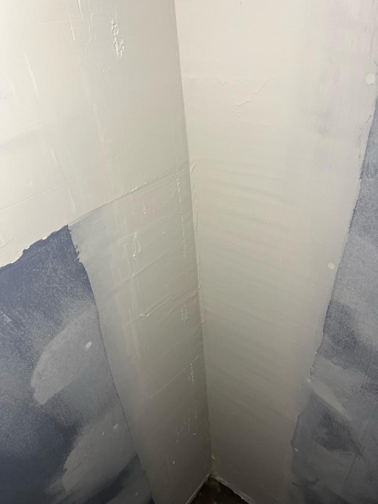
I can’t win on the new shop build… hired a contractor to finish my bathroom as I was loosing patience with myself and wanted it done. And here is the drywall he said is ready for primer and maybe a final sand. Paid a lot of money for this garbage but just wanted him gone at this point.

fc6ed4520df615b374bc2920a12ea4d2.jpg
 
Shotgun-I think I understand the drawing. But if the end cap is not in contact with the trunnion (i.e. there is a gap.) Then you will get some movement of the trunnion that is only limited by slop in the 4 screws that hold this cap? No? Also, this necessitates barstock > 3" diameter for the trunnion?
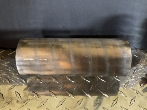
Jeff- Isn't the trunnion locked in place some how it the current design? I still think a thin bushing might solve the problem and also might make the movement of the trunnion more smooth. I found some brass pipe the is listed as 3" OD with a .125 wall. I am not sure if something like this could be used. Maybe knurl the OD and press fit it? 3" bronze bearing stock would work well but it is pricey.
Lanagos-Yeah that mud work looks terrible. I could have done that for free. Drywall mud is a true artform. When do you think you could have your mill sorted out? I wasn't even thinking about the engraving. That is outside my capabilities.

Edit: $75 is not terrible but it would be a lot of work to make the bearings. They could have a small flange as well.
 
Last edited:
Back
Top