Group Project: Rotary Broach-- Building complete, all shipped out!

My most realistic choice would be 12L14...great for machine tools and very machinable...

Yep, just about any steel would be perfect! I tend to best be able to hold dimensions in 12L14, so I'd lean toward that. Else I tend to use cold-roll (or 4140 when I'm feeling extra fancy).

What are the thread diameters and pitch?
3/8-24. If you want to use something else, the backing-plate is the one with the threaded hole in it, so you can do yours differently :)

I chose 3/8-24 since it had the widest range/variety of options, from MT1 to MT4, as well as R8 and a bunch of straight shanks.
 
The material I have is unknown for sure. Ferric Unknownium. :grin:

Some steel anyway. If everyone would prefer something else, I can likely find something..
 
I ordered 12L14 stock, says it will be here by 24th, but I suspect a couple days earlier.
I looked for an MT3 to 3/8” arbor, nothing on Amazon though there is a 14mm which is a bit beefier, maybe I’ll go that route…I’ll keep poking around.
 
I ordered 12L14 stock, says it will be here by 24th, but I suspect a couple days earlier.
I looked for an MT3 to 3/8” arbor, nothing on Amazon though there is a 14mm which is a bit beefier, maybe I’ll go that route…I’ll keep poking around.
I see this one for $12: https://www.amazon.com/Arbor-Drill-Chuck-Tang-Thread/dp/B01NBJGX2L

The keywords are basically "3/8-24 MTx Arbor" on google and that comes up with all the MT1-4 and R8 (plus many others).

3/8-24 is a really common drill chuck arbor thread, so they come up for those.
 
Weird, I searched for MT3 to 3/8” arbor and nada. Looking at that, it seems that recessing the threads in order to let the boss seat with inside of the backing plate would be ideal, but that would double thickness. I’ll stick to the plans…
 
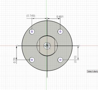
I'm dinking around with the step file and I'm a bit confused. I know there was discussion with offset an I just smiled and looked pretty as I had no idea WTH you guys were talking about. On this drawing, which mostly agrees with yours....is this strange hole pattern anything to do wit that?
I assume the body will have this spacing as well? I'm not seeing it on those plans. This seems error-ish (?)backquestion.jpg
**EDIT** going back to the prints (as for whatever reason-the computer version is blacked out) I see some notes as to this being by design. I stand by WTH, as I am perplexed as it's the 1 degree thickness the spindle spins on that causes the in/out cutting motion. I don't understand the hole offsets. This will only allow the body to bolt up one way...but why? Everything is centered on rotational axis. Should I continue to look pretty and just do as I'm told? I'm ok with the short answer....
 
Last edited:
I'm dinking around with the step file and I'm a bit confused. I know there was discussion with offset an I just smiled and looked pretty as I had no idea WTH you guys were talking about. On this drawing, which mostly agrees with yours....is this strange hole pattern anything to do wit that?
I assume the body will have this spacing as well? I'm not seeing it on those plans. This seems error-ish (?)View attachment 369432

Note that this seems to be 'on axis' rather than on-angle, the face is at a 1 degree angle, so I think the measurements might be a touch off. It is supposed to be biased 42 thou I think (so .742/.658?).

Holes are spaced in a 1.400 square. However, this square isn't 'centered', it is shifted "up" (in this case to the left?) on the 'thicker' side of the 1 degree angle. This offset moves the 'body' upwards (again, toward the thicker side of the backing plate) to make up for the 1 degree angle across the face. The idea is that the broach bit has to be 'centered' on the axis of the shank, but approach the material at a 1 degree angle.
 
Next question...body says it is drilled for 1/4 x28 4 bolt pattern (I don't believe it says tapped as well), but the back plate says 1/2 x 28 (which I can't find even existing on my calc program) and when I model in F360, that hole is way too huge for area. Should this be 1/4 x 28 in backing plate? It says clearanced so I assume it also is not threaded? No threads body, no threads plate? I promise I'm getting MOST my questions out now.
 
Next question...body says it is drilled for 1/4 x28 4 bolt pattern (I don't believe it says tapped as well), but the back plate says 1/2 x 28 (which I can't find even existing on my calc program) and when I model in F360, that hole is way too huge for area. Should this be 1/4 x 28 in backing plate? It says clearanced so I assume it also is not threaded? No threads body, no threads plate? I promise I'm getting MOST my questions out now.
Woops! Yeah, the bolt holes in the body should be drilled/tapped 1/4-28, and the backing plate should be clearance-drilled "G" (to allow a little wiggle/calibration room).

The bolts go through the backing plate, and into the 'main body' (which should be tapped for that). Other designs have bolts coming in from the front, but it results in the 'flange' needing to be significantly larger.
 
Back
Top