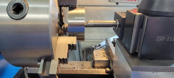
For the main bores in the body, is conctricity critical? I think one of the bores is going to be from the back, I can certainly center it in the 4jaw, just checking if I need to hold tight tolerance for it.
-
Welcome back Guest! Did you know you can mentor other members here at H-M? If not, please check out our Relaunch of Hobby Machinist Mentoring Program!
You are using an out of date browser. It may not display this or other websites correctly.
You should upgrade or use an alternative browser.
You should upgrade or use an alternative browser.
Group Project: Rotary Broach-- Building complete, all shipped out!
- Thread starter ErichKeane
- Start date
- Joined
- Jun 26, 2018
- Messages
- 1,733
@ttabbal I'm gonna say since bearings reside in the body, concentricity is important.
As far as wiggle room on holes in backing plate, I'm getting (reading) .250" to .266" on the 1/4" screws. I was thinking of counterboring them a bit...nay, yay?
Here is "close' and "loose" tolerance. I think since this is our first attempt at the theoretical, more wiggle room over less. If I hear no arguments from anyone, .266" is it.

- Joined
- Aug 3, 2017
- Messages
- 2,437
It isn't particularly important, a few thou Esther way is going to be fine. The rear bore is for the bearing, which is the only fixture holding the bit "centered". I intentionally did that to try to give us a little wiggle room in getting the offset right.For the main bores in the body, is conctricity critical? I think one of the bores is going to be from the back, I can certainly center it in the 4jaw, just checking if I need to hold tight tolerance for it.
I might suggest doing the .750 through bore and the rear most bearing bore in the same operation, since those are the most inportant concentricity wise. That .750+ is so that the spindle's .750- had a spot to go, so we might "miss" the bearing otherwise.
The front bore OD is a clearance hole for the thrust bearing, so it doesn't index on anything at all. If it is out of center or over spec, it won't matter one iota.
- Joined
- Aug 3, 2017
- Messages
- 2,437
I designed this like _I_ was making it, so there is basically 1-2 important dimensions on everything at mostCool. That helps. I would like to keep everything as close as possible, but there's always tolerance somewhere.
- Joined
- Jun 26, 2018
- Messages
- 1,733
I feel like I should be knocking these out now, but now that I have he ops down, its only a few hours work. I did measure the angle with a digital angle gauge of the "prototype" plate I made. I actually have (not the thickness) an angle of 89* and when I flipped it...91* but now I'm perplexed. Do I run at the .045" imbalance I purposely used or do I drop it down to .042" as planned. I can always remake mine real quick so I'll keep mine as is and we'll all compare notes I guess.
What steel did you use @ttabbal ?
What steel did you use @ttabbal ?
- Joined
- Jun 26, 2018
- Messages
- 1,733
Did I get the only to "important dimensions"?I designed this like _I_ was making it, so there is basically 1-2 important dimensions on everything at most
- Joined
- Aug 3, 2017
- Messages
- 2,437
I had figured you would use a sine bar to set the angle, it should be pretty straight forward I'd you have one. I've not considered what doing a angle gauge would do...I feel like I should be knocking these out now, but now that I have he ops down, its only a few hours work. I did measure the angle with a digital angle gauge of the "prototype" plate I made. I actually have (not the thickness) an angle of 89* and when I flipped it...91* but now I'm perplexed. Do I run at the .045" imbalance I purposely used or do I drop it down to .042" as planned. I can always remake mine real quick so I'll keep mine as is and we'll all compare notes I guess.
What steel did you use @ttabbal ?
- Joined
- Aug 3, 2017
- Messages
- 2,437
Each part has a couple.Did I get the only to "important dimensions"?Those bit have got to be a bit an the unforgiving side!
The backing plate has the angle + the offset.
The body has the OAL (well, back to the rear of the front bearing) and the rear bearing diameter.
The spindle has the 1/2" fit into the rear bearing, plus back of bit to back of front flange.
The bits have OAL plus the clearance angle plus the size of the bit hex.


