- Joined
- Jun 12, 2023
- Messages
- 41
Hello all
I am a new member and just starting out in the hobby.
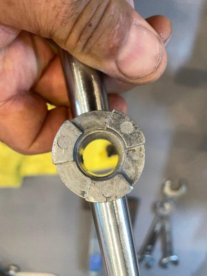
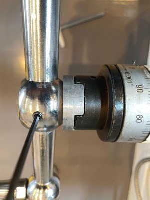
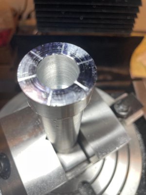
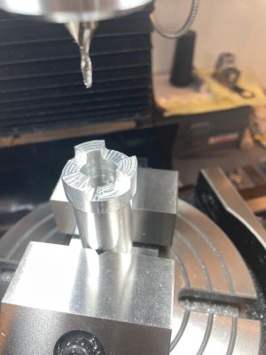
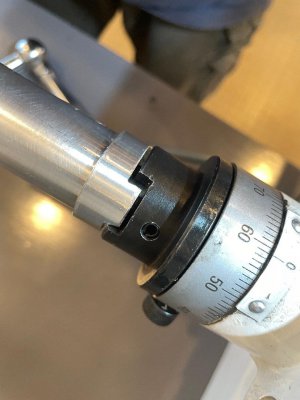
I purchased a mill and a lathe to start both PM, mill 932V, lathe 1236 and I am trying to make, new, longer, handles for the mill. I turned down the stock to the correct size drilled the proper holes using the lathe and proceeded to mill the ends of the extensions to match the machine. This is where I am having difficulties. I laid out the handle extension, set it up in a rotary table and messed it up basically. I indicated the rotary table locked the table, set up the extension, indicated it off the center bore, not moving the table or rotary table. Set up for 120 degree cuts, 6-60 degree 120 degree on center. I tried to fit the pieace from the original handle into my new part and it did not fit. I then proceeded to remove material to get the existing handle to fit the new extension.
That's where I think I am loosing the dimensions. once I get the existing handle to fit the new extension the new extension don't fit where the existing handle is suppose to fit. My new piece is sloppy in the existing location. It works but don't look good.
I attached some pictures to illustrate.
Any advise on my procedure, set up, lay out, old age and inexperience is greatly appreciated.
Thank you all
I am a new member and just starting out in the hobby.
I purchased a mill and a lathe to start both PM, mill 932V, lathe 1236 and I am trying to make, new, longer, handles for the mill. I turned down the stock to the correct size drilled the proper holes using the lathe and proceeded to mill the ends of the extensions to match the machine. This is where I am having difficulties. I laid out the handle extension, set it up in a rotary table and messed it up basically. I indicated the rotary table locked the table, set up the extension, indicated it off the center bore, not moving the table or rotary table. Set up for 120 degree cuts, 6-60 degree 120 degree on center. I tried to fit the pieace from the original handle into my new part and it did not fit. I then proceeded to remove material to get the existing handle to fit the new extension.
That's where I think I am loosing the dimensions. once I get the existing handle to fit the new extension the new extension don't fit where the existing handle is suppose to fit. My new piece is sloppy in the existing location. It works but don't look good.
I attached some pictures to illustrate.
Any advise on my procedure, set up, lay out, old age and inexperience is greatly appreciated.
Thank you all