Having problem milling 120 degree sections

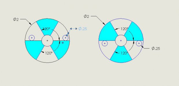
My previous post was in error. As @benmychree e states the first cut can be made by milling completely through the part. Then rotate 120º to make the second pass and 240º for the third pass. The rotate to 60º and offset by the cutter diameter to the opposite side of the centerline and make the fourth pass. Rotate 120º for the fifth pass and 240º for the final pass. Hopefully, the diagram below will clarify.
Circle  Sector.JPG
 
Thank you extropic

As for the second post, there are 3 handles on the machine. They all interchange with each other. For the first post I will need to check. I am not sure of that, so that could be an issue. I will follow up on this observation shortly.

Thank you
 
Thank you RJSakowski

I kind of did that except I made 6 separate cuts along each face, offsetting for tool diameter as shown. FYI tool is .125" diameter, .0625" radius. Sorry if I gave the impression it was .250'

Thank you following up with a diagram, I probably would have typed a word salad trying to explain that.

I am also going to look at extropic concern as well. But to your point and benmychree that is what the handbook for calculating arch angle gives for lay out. So that is how I laid out the dimensions.
 
Thank you extropic

I checked the original as you suggested they are not as I laid them out, or per the hand book. Thank you for observing that detail.

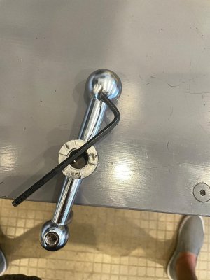
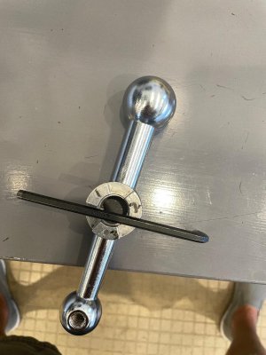
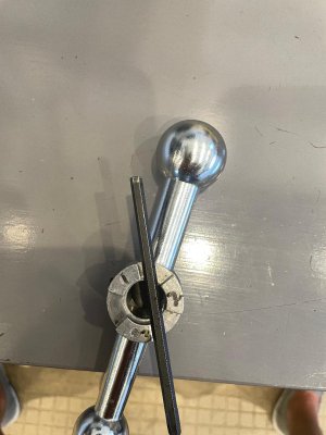
The Allen wrench is up against one of the shoulders of the clutch in each photo. They were close and small enough to fit between the sections, sorry for improvising.

Now I need to figure out what those angle are.


Thank you
 

Attachments

  • original angles 1.jpg
    original angles 1.jpg
    117.8 KB · Views: 46
  • original angles 2.jpg
    original angles 2.jpg
    116.8 KB · Views: 45
  • original angles 3.jpg
    original angles 3.jpg
    110.7 KB · Views: 45
I think you have the correct info.

I'm going to add that you should not use a small cutter like that. Use a larger diameter, it is less prone to breaking off, and will cut nicer. With a small cutter you need to take more passes, need more rpm, and risk the tool. Figure out what the largest size cutter you can use and still take a fraction of a cleanup pass at the end.

Welcome to HM.
 
Sorry all I'm sure the formula in the hand book will allow for any angle.

Thank you
 
Thank you woodchucker

I did have to run a lot of passes, I have larger end mills I will check to see.

Thank you
 
Thank you extropic

I checked the original as you suggested they are not as I laid them out, or per the hand book. Thank you for observing that detail.

The Allen wrench is up against one of the shoulders of the clutch in each photo. They were close and small enough to fit between the sections, sorry for improvising.

Now I need to figure out what those angle are.


Thank you
The angles look to be the same, the two surfaces not lining up could be clearance cut into it on one side instead of evenly spread on both sides. Does the receiver on the mill look offset like that too?
 
Thank you Ischgl99

I would assume they are but I made that mistake on the first 2 layouts. I will check that when I get back on the machine. I have not laid out the original piece on paper nor have I tried to figure out the angles they cut to form it. It appears to be a cast piece. There are 3 total on the machine. Two are identical short, 1", adapters for the X axis and one that is about 3" long for Y axis. The 2 short ones are aluminum and the longer one is steel. I will start looking at it in more detail to try to figure out what they did to produce them. I appreciate this forum greatly and all the assistance from its members. I'm not sure I would have caught that for a long time if ever. My hats off to everyone that replied.

Thank you
 
As to how the original is made, it is die cast, the giveaway is the ejector pin marks on each of the 3 tabs.
I just found this thread and the first thing I noticed was that the edges did not go thru the center of the part.

If you have a CAD program it is easier to lay it out to find the angles.
Draw the OD and the ID. Draw a chord line across the OD circle. Measure and then dimension the length of the chord.
Now do the same for the ID. Connect the ends of the chord lines and you will have your angles. and any other dimensions you will need.
Check all 3 tabs to be sure they are the same. Check the width between the tabs to be sure they are al the same.
While laying it out use the average of all 3 tabs.
Remember to allow for the radius on the corners in your measurements. the corners do have a radius and if you draw it the same dimensions to sharp corners your calculations will be off.
 
Back
Top