Having problem milling 120 degree sections

Thank you Flyinfool

I do have a really old version cad lite on a laptop somewhere. I will need to find it. I’m not the best at it but I do understand what you are explaining. Math and geometry are not my strong points. But I think they will be after getting into the hobby.

Basically measure the inside/outside dimensions of each segment and lay it out and connect the two to get the angles.

Lay out those dimensions on the new piece and set up for each cut. The rotary table probably isn't much good I don't think since the angles are not through the center. That could just be my lack of knowledge and experience in this case, but its no problem setting up each cut separately.

I was going to research the hand book to try to figure out the best way to determine those angles but this advice pointing in the direction I needed to do that. Greatly appreciated

Thank you
 
I would still use the rotary table. You rotate to line up with the surface you want to cut and the CAD can tell you the offset from center. You can even draw in your cutter diameter to have the cad tell you the exact X and/or Y offsets from center of rotary to center of cutter that you will need. I do this all the time, it works great.

Here is a part that I did recently.

It was set up on the RT centered on the center of the big Dia with the tab on the X axis.

Sheet 1 is the drawing of the finished part.

Sheet 2 is the first pass with a 1/2 "roughing" mill. You can see that I have the center line of the cutters travel drawn and dimensioned including rotation angles for the RT.

Sheet 3 is the finish pass with a 1/32 end mill. again the full tool path is drawn and dimensioned.
 

Attachments

  • DH 010 Sector Bottom.pdf
    134.5 KB · Views: 17
You could place it in the rotary with a partig tool bar against a tooth like you have your Allen.

Then with a DI I your spindle, adjust the rotary so the angle matches.

Cut and repeat..

Sent from my SM-G781V using Tapatalk
 
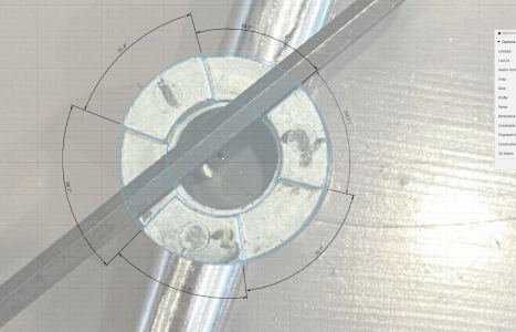
I put one of the pictures with the Allen wrenches into Fusion360 and made a sketch from that, none of the angles match. I got 64, 67, and 70 for the angles of the recesses. Only one of the angles appears to go through the center point, so I have no idea how they made the mold for this thing. Some of that will be errors with the perspective not being exactly overhead, but they are far enough off that it appears this was not made to any standard dimension that you can easily repeat. It might be easier to make a new extension and driven piece on the leadscrew instead of trying to replicate this item. Or, if the piece on the leadscrew is screwed up like this, you can cut the teeth smaller to a consistent dimension and then make a new extension that matches what you made.

Capture.PNG
 
Thank you all

I looked at Jeff Stuff Drawing and would like to ask, if I compensate per drawing am I not still referencing center of piece? That would give me the same cuts I am producing now. The angles are not through center so each cut is a different orientation off center. I think they are still 120 degree separation on each segment but the design is something off of center. I did go out and sketch the existing piece so I can try my hand on CAD. It's been at least 15yrs that I have done anything with that program so it will be awhile getting acclimated again. I will try to lay out as Flyinfool suggested in his earlier post. I have the measurement of each segment inner and outer and have the ID and OD as well. I just need to get the time to start playing on CAD.

I think I am understanding this a little better and realize why I have been having such a hard time replicating the piece. I'm old but I was wondering if I was starting to lose my faculties here.

Thank you all again
 
@want2drive
From the Fusion360 work that @Ischgl99 provided, I averaged the angle values and get 67.03° for the protrusions and 52.67° for the slots.
It's still not clear whether the plane of the slot walls include the central axis (it doesn't look like it) or are offset.
Assuming you have a digital, dial or vernier caliper, you could hold the hex key tightly against one wall and measure the major distance between the key and the wall of the central hole. The difference between that dimension and the radius of the hole equals the offset.

It should be noted that there may be some draft angle in the walls to facilitate releasing from the mold. I hope you're prepared to ignore that small potential mismatch.
 
@Ischgl99 That's cool what you did with Fusion360.
I came across this technique on YouTube a year or so ago and glad I remembered it. You basically import a picture of something, then you create your sketch over top of it. You can calibrate it too so that you get real dimensions from it. For that, you would take the OD for example, measure on the part you have, then calibrate the picture to the sketch, then you would have dimensions of everything else as accurate as you can match up the drawing to your sketch.

@want2drive
From the Fusion360 work that @Ischgl99 provided, I averaged the angle values and get 67.03° for the protrusions and 52.67° for the slots.
It's still not clear whether the plane of the slot walls include the central axis (it doesn't look like it) or are offset.
Assuming you have a digital, dial or vernier caliper, you could hold the hex key tightly against one wall and measure the major distance between the key and the wall of the central hole. The difference between that dimension and the radius of the hole equals the offset.

It should be noted that there may be some draft angle in the walls to facilitate releasing from the mold. I hope you're prepared to ignore that small potential mismatch.
When I was doing the sketch, it looked like only one of the angles went through the center, but that could have been because of the perspective of the photo being at a slight angle to the center.
 
When I was doing the sketch, it looked like only one of the angles went through the center, but that could have been because of the perspective of the photo being at a slight angle to the center.

We are shooting in the dark here, but asymmetry makes no sense to me so I choose to assume symmetry and investigate the offset. Your graphic was a big help. I do miss not having unlimited access to top drawer CAD.
 
We are shooting in the dark here, but asymmetry makes no sense to me so I choose to assume symmetry and investigate the offset. Your graphic was a big help. I do miss not having unlimited access to top drawer CAD.
Normally I would assume things would be symmetric as well, but I’ve learned to never assume anything with Chinese products. I’m hoping the problem is something with how they did the offset. I am curious what the piece on the lead screw shaft looks like and if it has the same offset or nonstandard angles we are seeing on this piece. If @want2drive has a scanner he can put the handle flat on, it might give a better picture to take angle measurements.

Fusion 360 is free for hobbyists, you just need to register for the download since they give you a year license for free. It has a steep learning curve, but there are plenty of videos on YouTube to show you how to use it.
 
Back
Top