- Joined
- Dec 18, 2019
- Messages
- 6,464
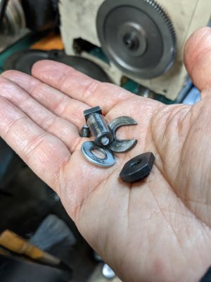
Recently bought a 6" Vertex Rotary Table, the HV-6. Made some tee-nuts to fit the table slots. Also blued the tee-nuts. Yesterday, received an 8" diameter 0.85" thick piece of 6061 for the fixture plate. The day before, I received an MT2 soft arbor, to act as the position locator.
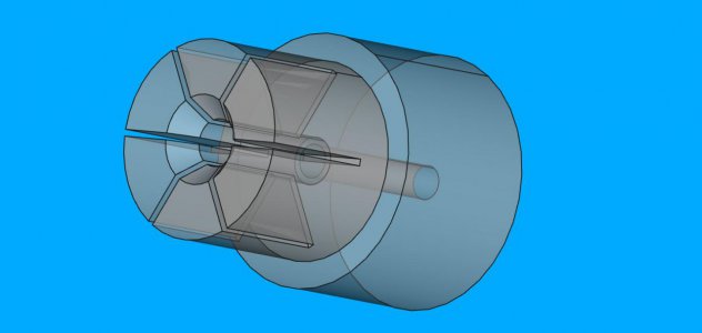
While I was waiting for the HV-6 to arrive, I designed a fixture plate for the table. From the dimensions of the table, it seemed that an 8" fixture plate would fit on it without fouling. So made a design in FreeCAD for the plate. Here's a top view.
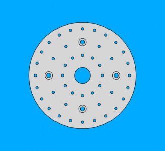
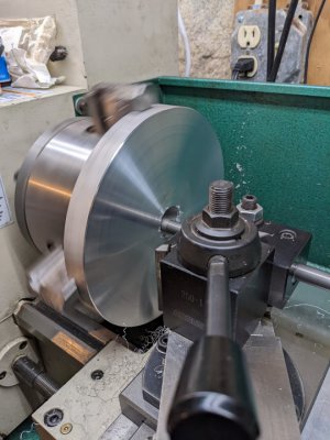
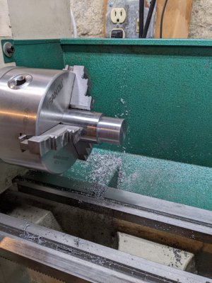
Nothing too fancy, but since it is a radial design, I will need to drill the holes while mounted on the table. Anyways, today was the day to start machining the plate. Managed to just barely fit in on my 6" four jaw chuck on my Grizzly G0752Z/G0602. There is maybe 1/8" clearance between the edge of the jaws and the ways. Really made me think if I wanted to try this.
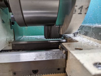
Screwed up my courage, hand rotated the chuck, checked all four jaws for clearance, set the speed for minimum, and turned on the lathe. Faced off both sides so far. Honestly, it was kind of scary since the second face was pretty uneven, and the cut thumped. But, I took it slow, and trued up the faces. Used some TCGT inserts which cut aluminum beautifully, if I do my part. Once the faces were true, I took a finish cut. As I got closer to center, I sped up the lathe some to improve the finish. I was nowhere near the recommended cutting speed since I was a bit concerned about those chuck jaws, but the sharp edged TCGT inserts seem to be tolerant of SFM. I wasn't getting nice chips, but they were manageable if I repetitively paused during the cross feed. Since this is a manual lathe, and my hand gets tired after a while, it worked out fine.
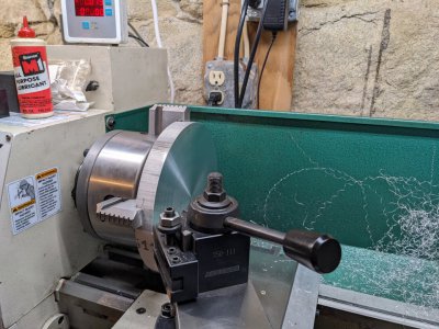
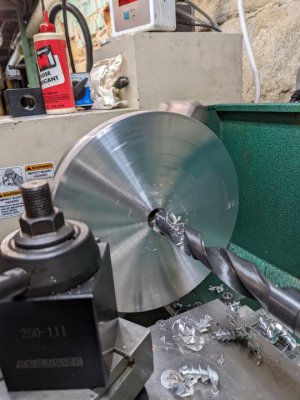
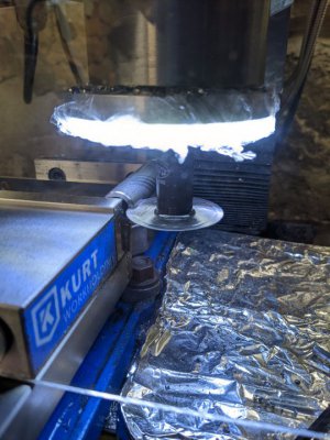
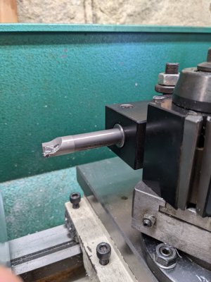
After lunch, have to figure out how to get the tool close enough to chamfer the edge. Once that is done, the next step is to drill out the center, and bore it to 30 mm. Hoping that goes smoothly.
While I was waiting for the HV-6 to arrive, I designed a fixture plate for the table. From the dimensions of the table, it seemed that an 8" fixture plate would fit on it without fouling. So made a design in FreeCAD for the plate. Here's a top view.

Nothing too fancy, but since it is a radial design, I will need to drill the holes while mounted on the table. Anyways, today was the day to start machining the plate. Managed to just barely fit in on my 6" four jaw chuck on my Grizzly G0752Z/G0602. There is maybe 1/8" clearance between the edge of the jaws and the ways. Really made me think if I wanted to try this.

Screwed up my courage, hand rotated the chuck, checked all four jaws for clearance, set the speed for minimum, and turned on the lathe. Faced off both sides so far. Honestly, it was kind of scary since the second face was pretty uneven, and the cut thumped. But, I took it slow, and trued up the faces. Used some TCGT inserts which cut aluminum beautifully, if I do my part. Once the faces were true, I took a finish cut. As I got closer to center, I sped up the lathe some to improve the finish. I was nowhere near the recommended cutting speed since I was a bit concerned about those chuck jaws, but the sharp edged TCGT inserts seem to be tolerant of SFM. I wasn't getting nice chips, but they were manageable if I repetitively paused during the cross feed. Since this is a manual lathe, and my hand gets tired after a while, it worked out fine.

After lunch, have to figure out how to get the tool close enough to chamfer the edge. Once that is done, the next step is to drill out the center, and bore it to 30 mm. Hoping that goes smoothly.


