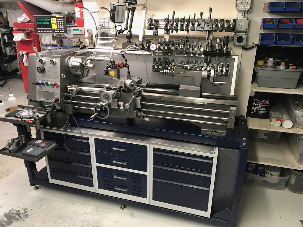
Some pictures of my PM-1340GT setup on a base that I shamelessly copied with some modification from David Best original design. The lathe uses a VFD system that was built for me by Mark (MKJS).
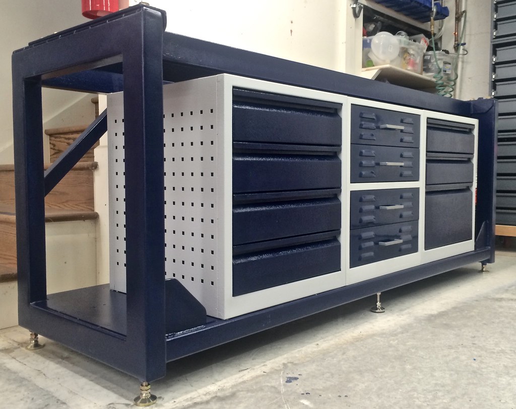
For drawers in the base I used Harbor Freight
56 In. Double Bank Top Chest. I removed and flipped the top cover and installed three
20 Inch 500LB Capacity Heavy Duty Full Extension Ball Bearing Side Mount Drawer Slides so I can have another high capacity drawer on the top. I still need to finish painting the additional 5 sheet metal drawers. I also copied David's idea for the tool holders but somewhat simplified the individual mounts by using aluminium angle cut sized and shaped to accept the BXA tool holders instead of David's design with dowel pins, I was lazy, I wanted to do something quickly.
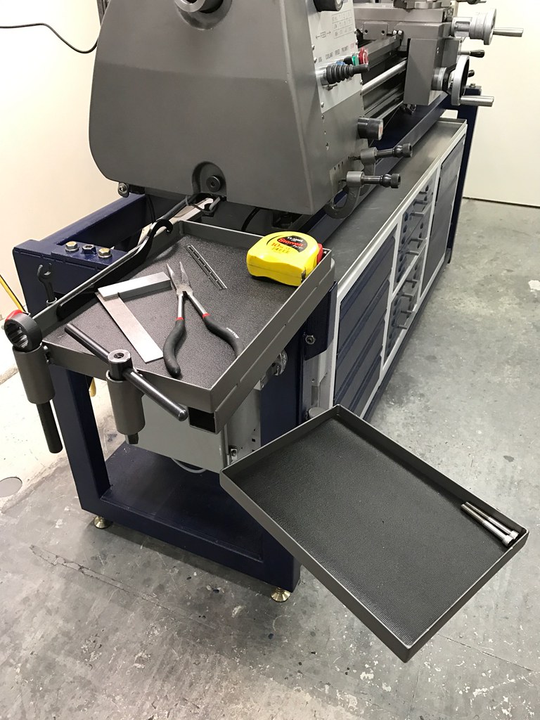
I used the original chip/oil tray that came with the lathe and modified it (shortening and sealing the holes) to be used as a slide out chip tray under the lathe.
I am very happy with the final result. It is at the right height for me (I am 6'2" in the morning...). It makes excellent use of the space/volume under the lathe with easy access. It is rock solid and adjustable for removing any twist in the lathe bed. The fabrication of the base was a very satisfying project, I used a MIG welder and made an extensive use of my 24" x 48" CertiFlat welding table. I used a high temperature 2 component epoxy paint to paint the base and this was much less fun but doable...
The VFD by Mark Jacobs works extremely well, was easy to integrate and Mark brings a treasure trove of knowledge that he is very happy to share.
View attachment 388103
I managed to squeeze in 4 additional drawers on the right
View attachment 388104
Flipped top cover made into a drawer. VFD is on the left of the drawer chest. One shot oiler is not hooked up yet to the lathe
View attachment 388108
Good space inside the drawers for a full set of 5C collets
View attachment 388109
View attachment 388105 View attachment 388107
Tool holders and backsplash support
View attachment 388106
BXA holders
Big thank you to David and Mark for their inspiration and help. Also thanks for the many other ideas that I received from multiple answers to my questions and from posts by many H-M members.
Ariel