- Joined
- Jul 2, 2022
- Messages
- 49
I got a seat of the Solidworks CAD system for Christmas (whooah!) and in the middle of January I started modeling the Atlas 618 lathe (serial number 011120) that a friend gave to me a while back. The lathe is now completely disassembled and the parts are being measured using hand tools like machinist scales, dial calipers, micrometers, and a tape measure. I have been working steadily on it and am getting near the end of phase 1, which is creating the basic model. Phase 2 is checking dimensions, fits, and tolerances. Phase 3 is drawings of selected parts. Phase 4 is solid models of selected parts for 3D printing. Below are some images of the lathe and the model so far. I couldn't find any reference on the site for what size is recommended for direct embedded images, so I hope these are OK. The things I could use some help about are at the end.
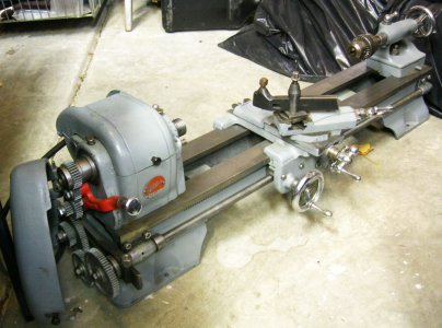
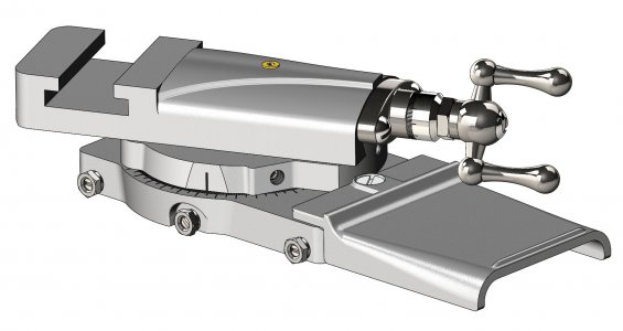
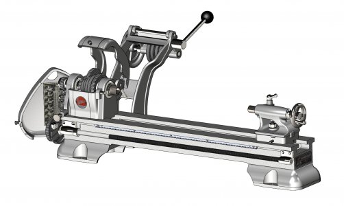
I could use some guidance in the following areas:
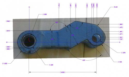
Is this fun, or what?
Thanks for any assistance you can give.


I could use some guidance in the following areas:
- Atlas/Clausing drawings. The only really useful one I have is for the spindle. These will be used to check my guesswork on items that were difficult or impossible to measure with the tools I have available. If anyone has images of any drawing for this lathe that is not already on this website, I would be glad to obtain a copy. Just about any digital format will do.
- Does Atlas/Clausing still provide digital images of drawings for this lathe? If so, a phone number and contact would be helpful.
- As long as I have the machine apart, I think I will paint it and I think I want to use a machine paint that can be brushed on. Recommendations as to paint type or application technique or experiences related to this would be welcome. For example, after cleaning a cast iron casting and prepping for paint, which means removing any lubricants such as grease and oil, how can one prevent rust from forming on the unpainted areas while the paint is curing?
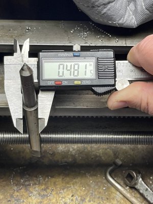
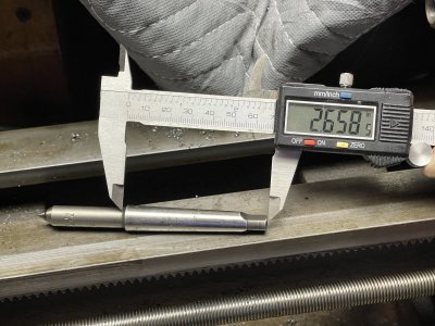
- There are a few parts that I do not have. If you would be willing to send me measurements of any of the following, that would be great.
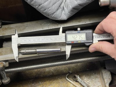
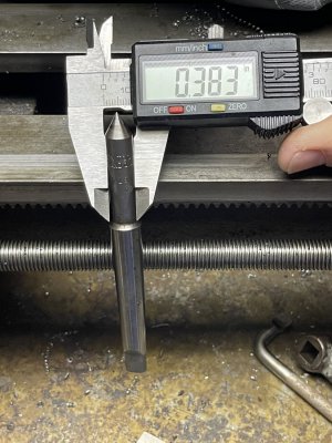
- 9-88 MT2 dead center from the M6-31X spindle assembly
- L2-80 MT1 dead center from the M6-5X tailstock assembly
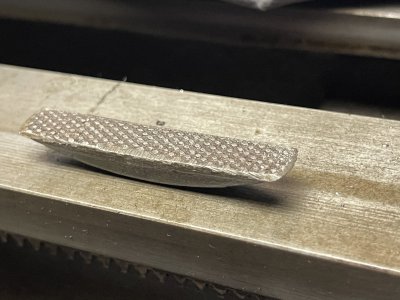
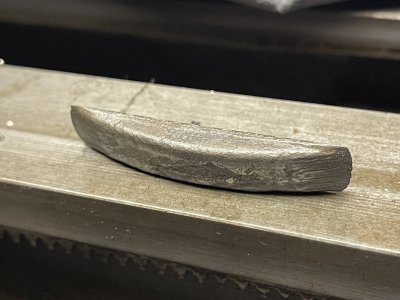
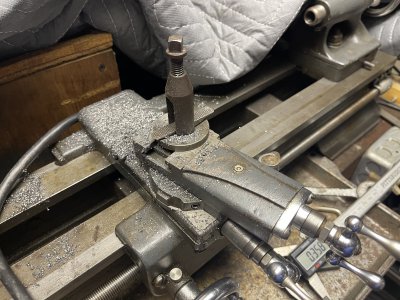
- 9-41 toolpost rocker from the M6-39X tool post assembly
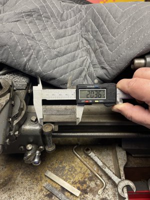
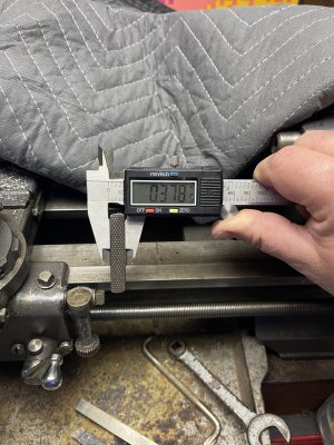
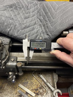
- I have the ability to scale a photo to determine measurements using the CAD system. A photo of one or more of these parts with a reasonably accurate measurement of the part's longest dimension can be used like a crude optical comparator. It works best if the photo is taken from a distance, at least 6 feet and the farther the better, to reduce optical distortion. Example below.

Is this fun, or what?
Thanks for any assistance you can give.


