- Joined
- May 3, 2020
- Messages
- 229
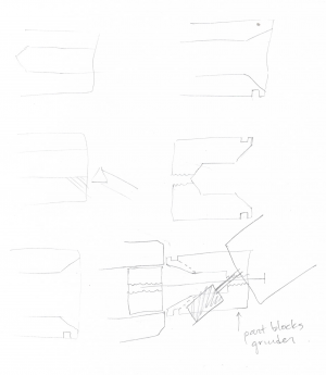
Started on the adapter. I don't know what's taking me so long. A bunch of new operations, maybe, lots of unknowns. Anyway, here's the plan:


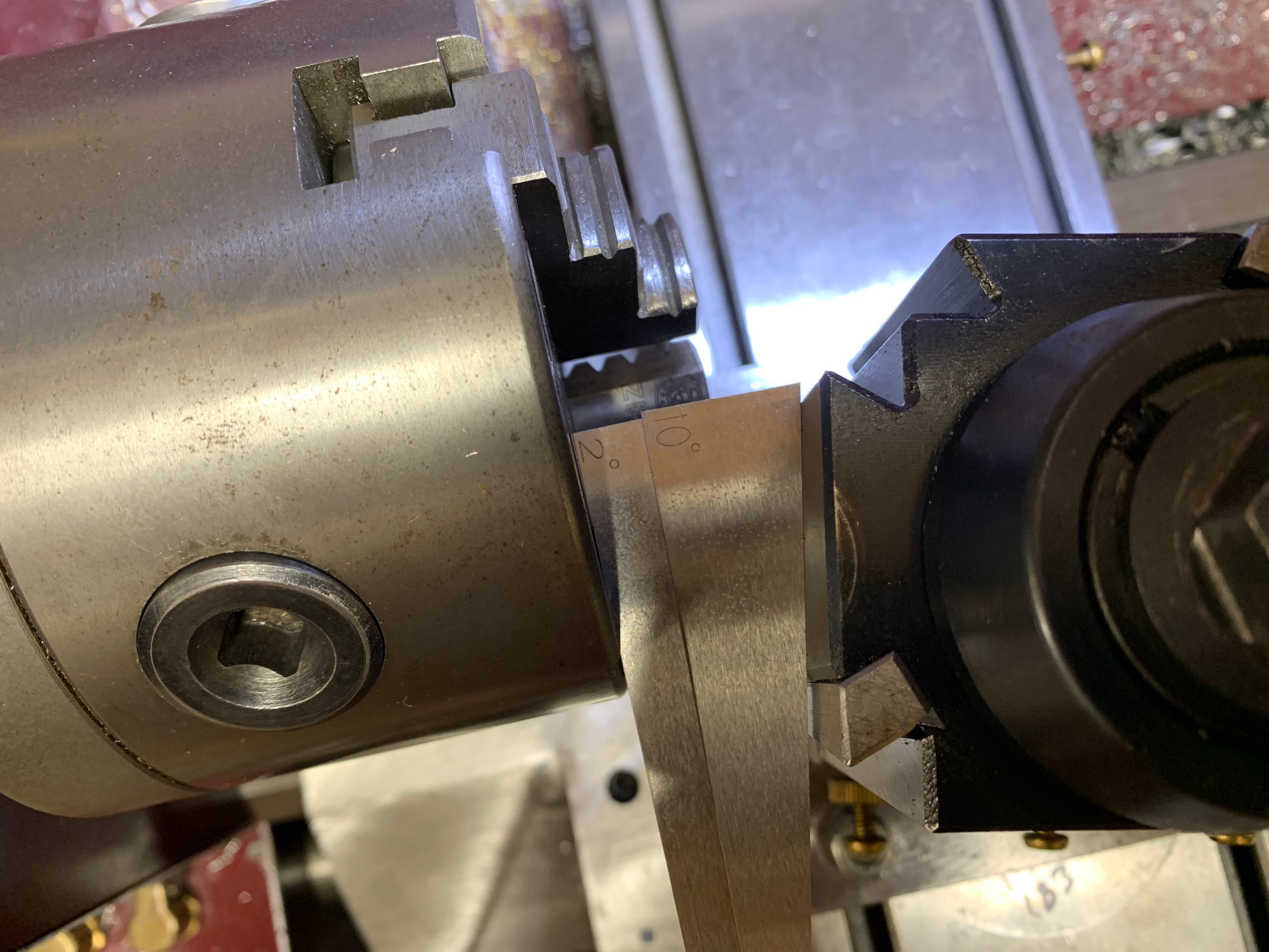
Setting the angle on the compound accurately is my next problem. I decided to do the trig method where you measure the legs of a triangle. The ways are 1 leg and the other leg is perpendicular. I'll move the carriage x along the ways and adjust the compound until the tool post moves by the right amount in y. The tool post will be square to the chuck for this operation. Whatever I use for x, y = x * tan(angle). Tangent isn't too crazy for small angles so I hope this works. Other methods might be more accurate. If I don't get a good print, I may need to use a different method.
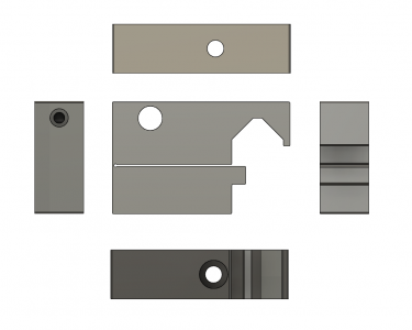
For now, I need some carriage stops to control the length of the x leg and I'll use an indicator against the took post to measure the other leg. I was going to buy a carriage stop but one of the first things I saw was this 3-d printed thing and he wanted 45 $ for it. Seems like a lot. Also, this is one of those basic projects that you're meant to do for yourself. So I decided to make a pair.

It's un-filled ABS with a 3/8 hole for drill rod or an indicator and a 1/4-20 clamp for the dovetail. The hinge is integrated into the body. It's 50% filled, which is fairly stout. I bought knobs from McMaster and some "press-fit" threaded inserts. After shipping and the extra parts, it was 42 $ for 2 stops.
BTW, I'm not a fan of the 3-d printing hype and various trinket printing that goes on. If I had a working mill, I would make this out of brass or aluminum and feel smug about it. But for now, the plastic version will have to do. I do not intend to over use the FDM printer (partly due to all the clucking) but I've been surprised at where it can be used effectively. I'm keeping an open mind while simultaneously resisting expectation of The Internet by not printing Groot. if you're quietly thinking about how this could be better done in metal---you're right. And I'll get there someday. Possibly by the end of this build.


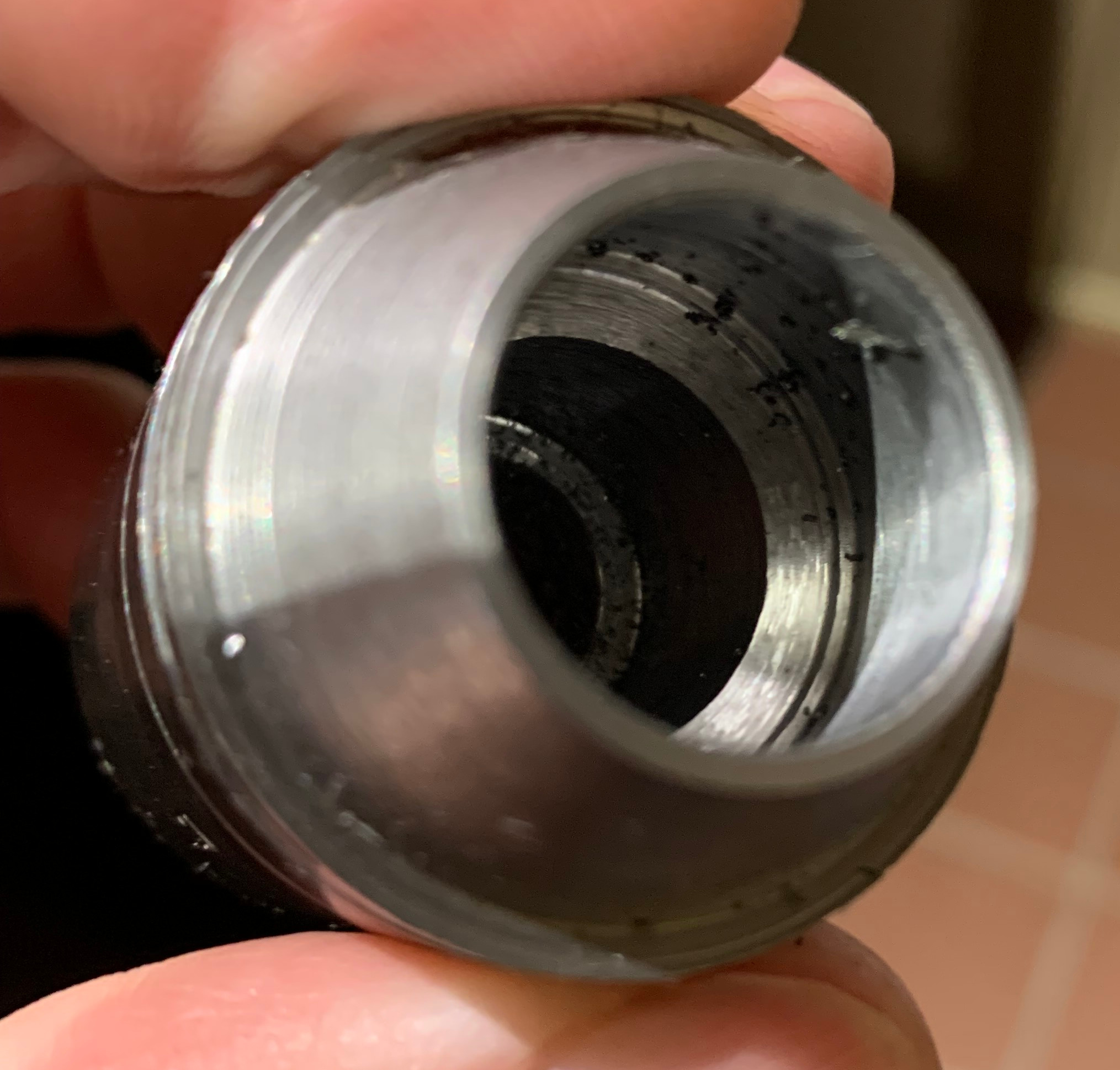
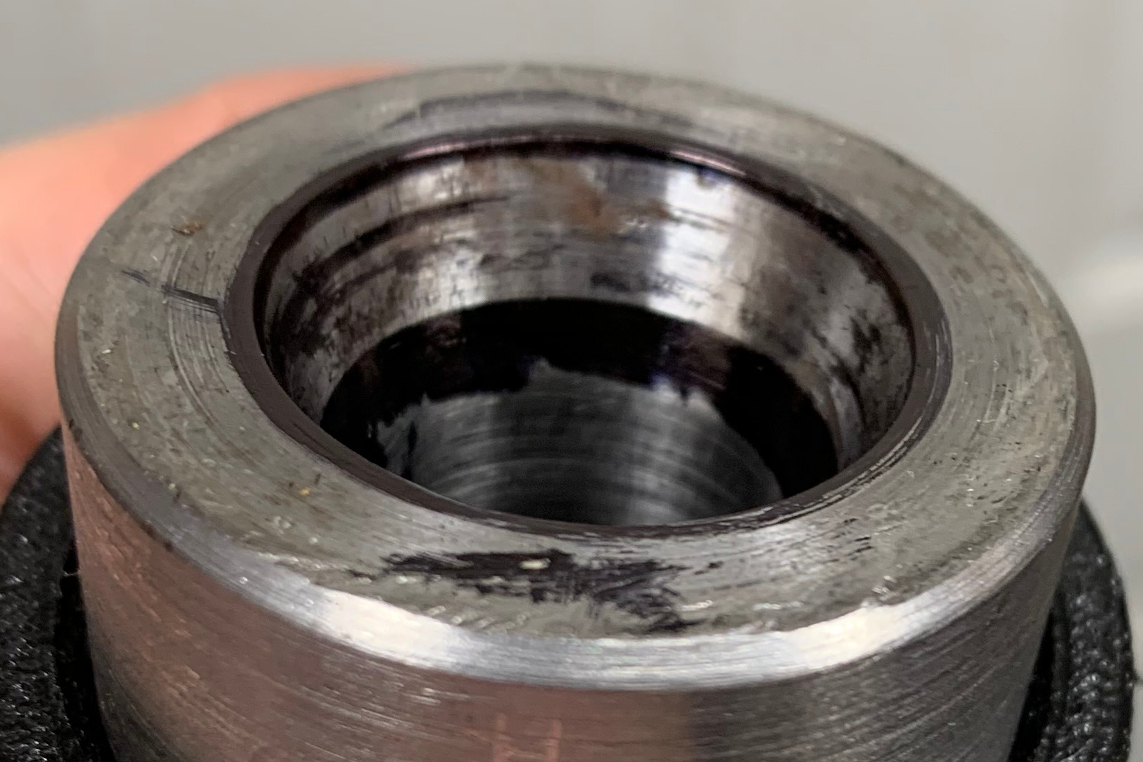
- Center drill, step up to 0.250, 0.400, 0.500, then bore to 0.650
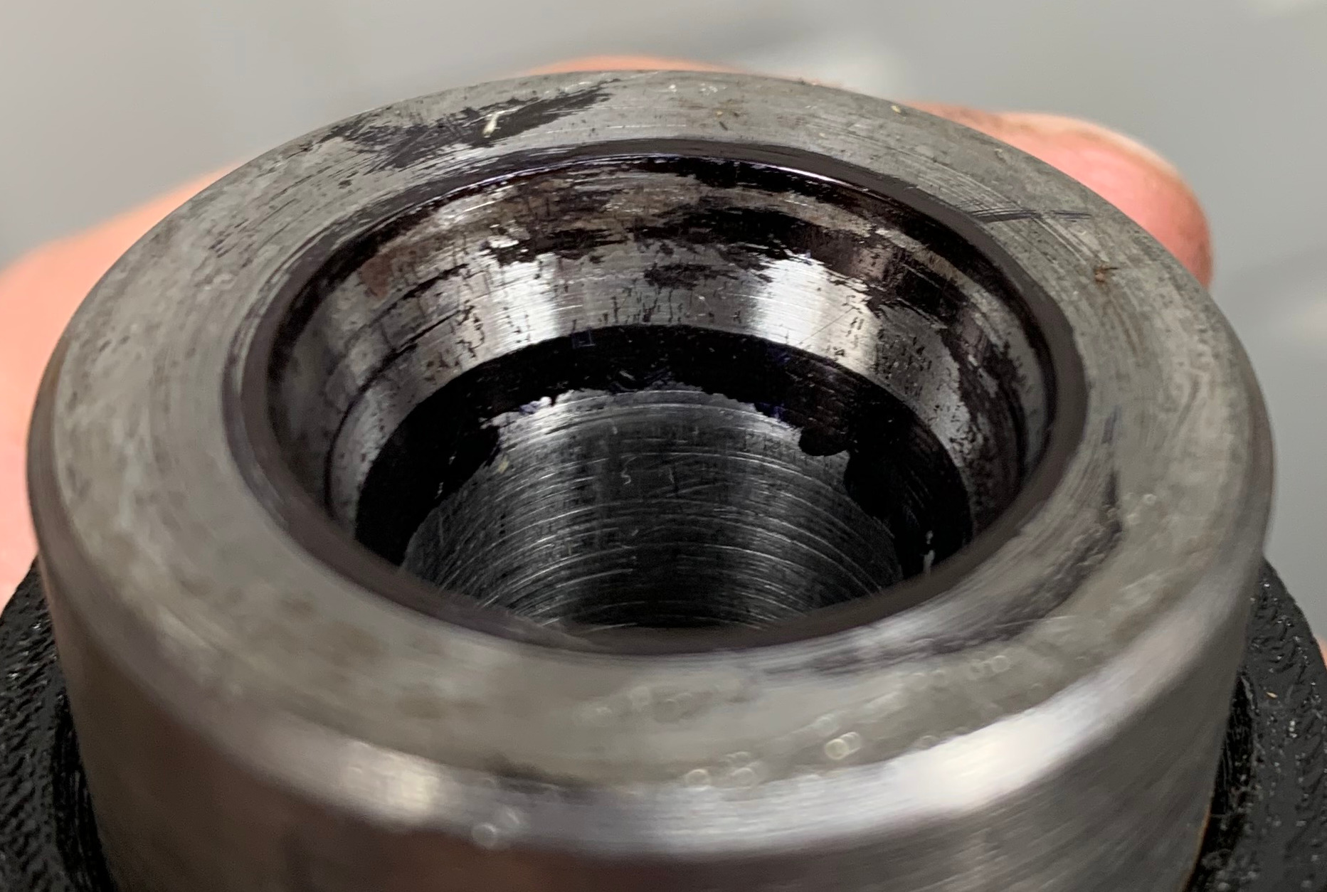
- Dust off compound, set to 12 degrees, and bore ID that will accept 3C collets
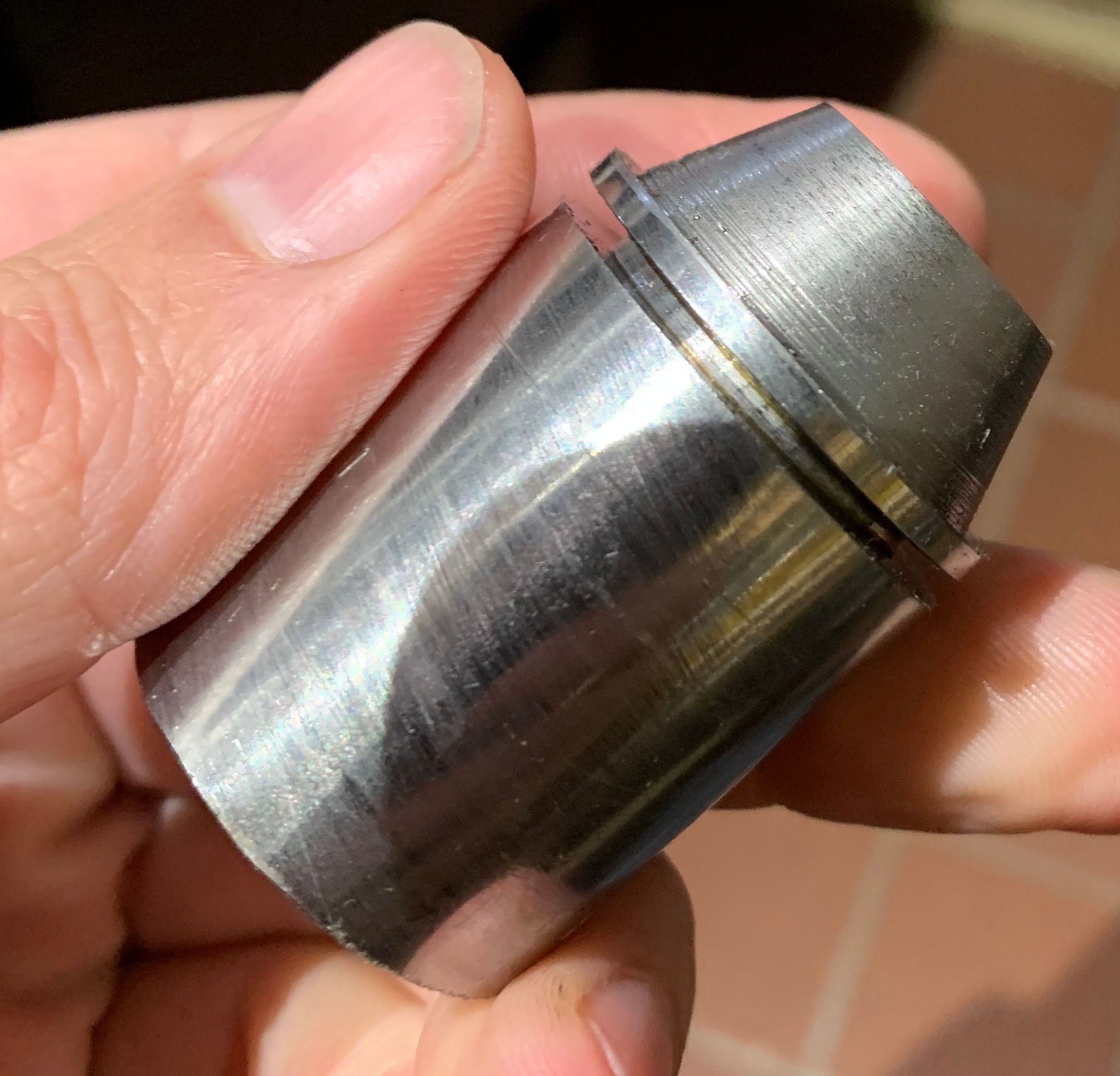
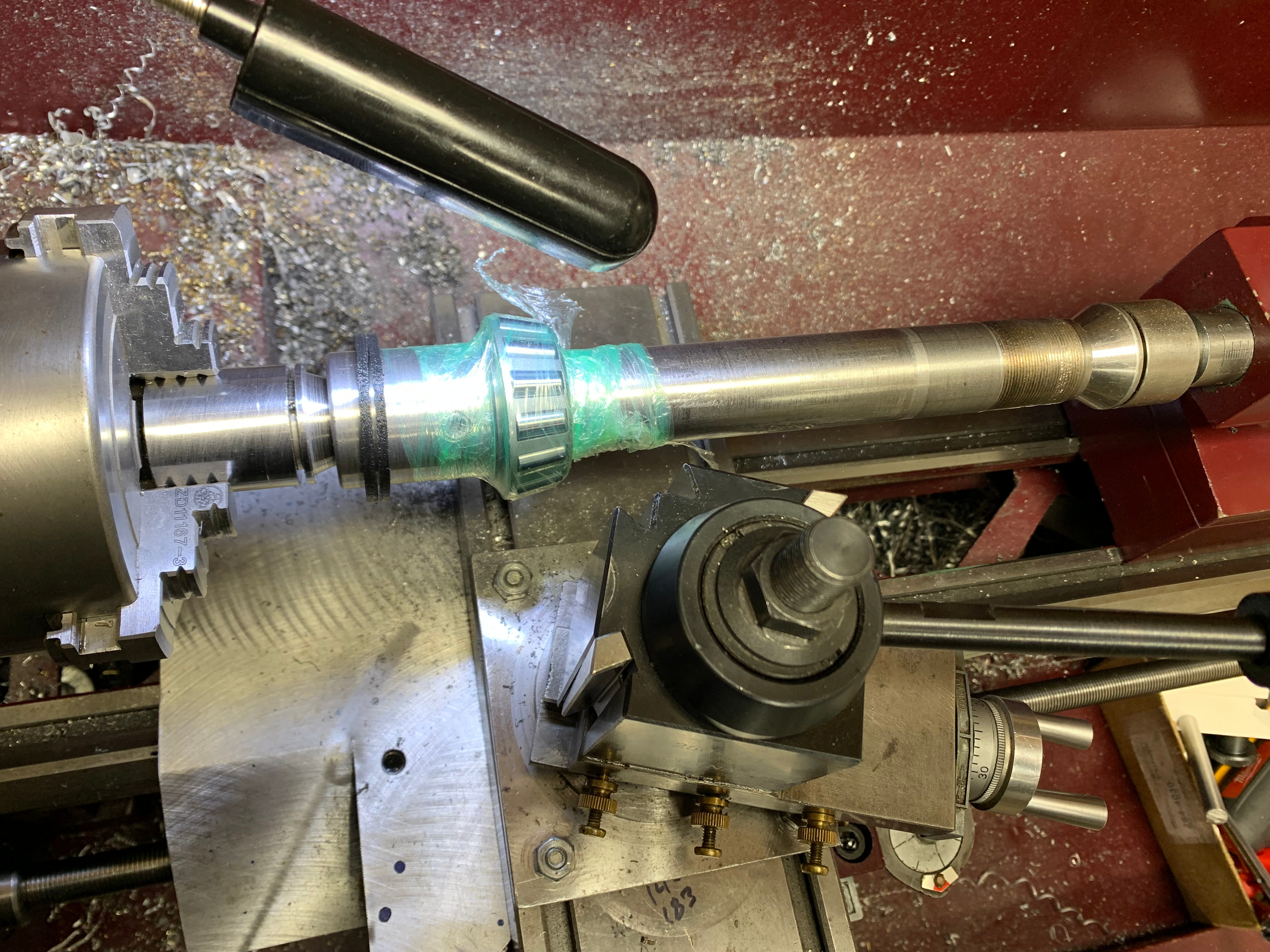
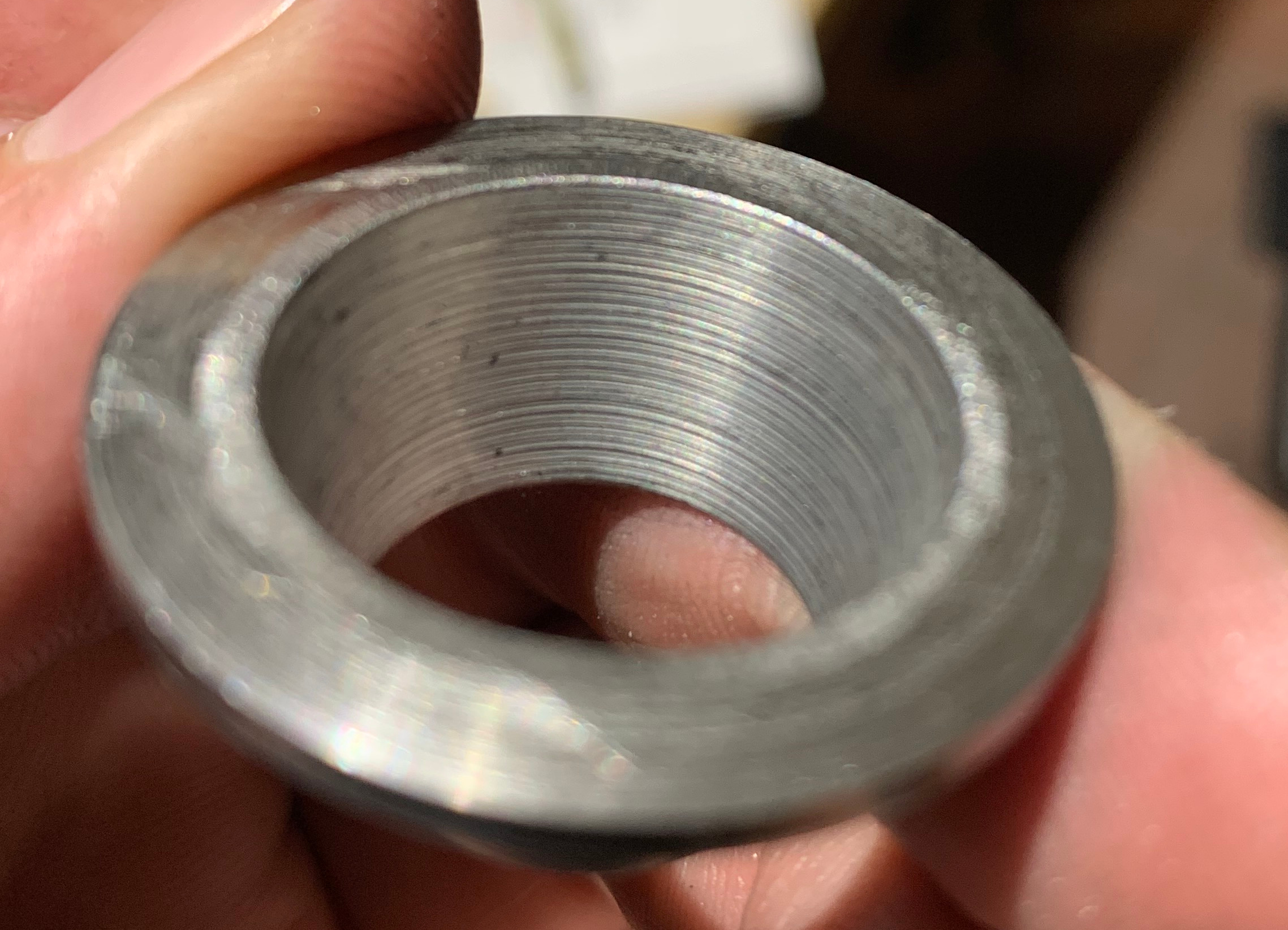
- Set compound to 20 degrees (to match spindle) and machine OD
- Turn flange
- Part off
- Heat treat O-1 and draw to R_C 58 (click here for history and details of the alloy)
- Make a split-ring collar to set the depth in the chuck, holding the part by the flange
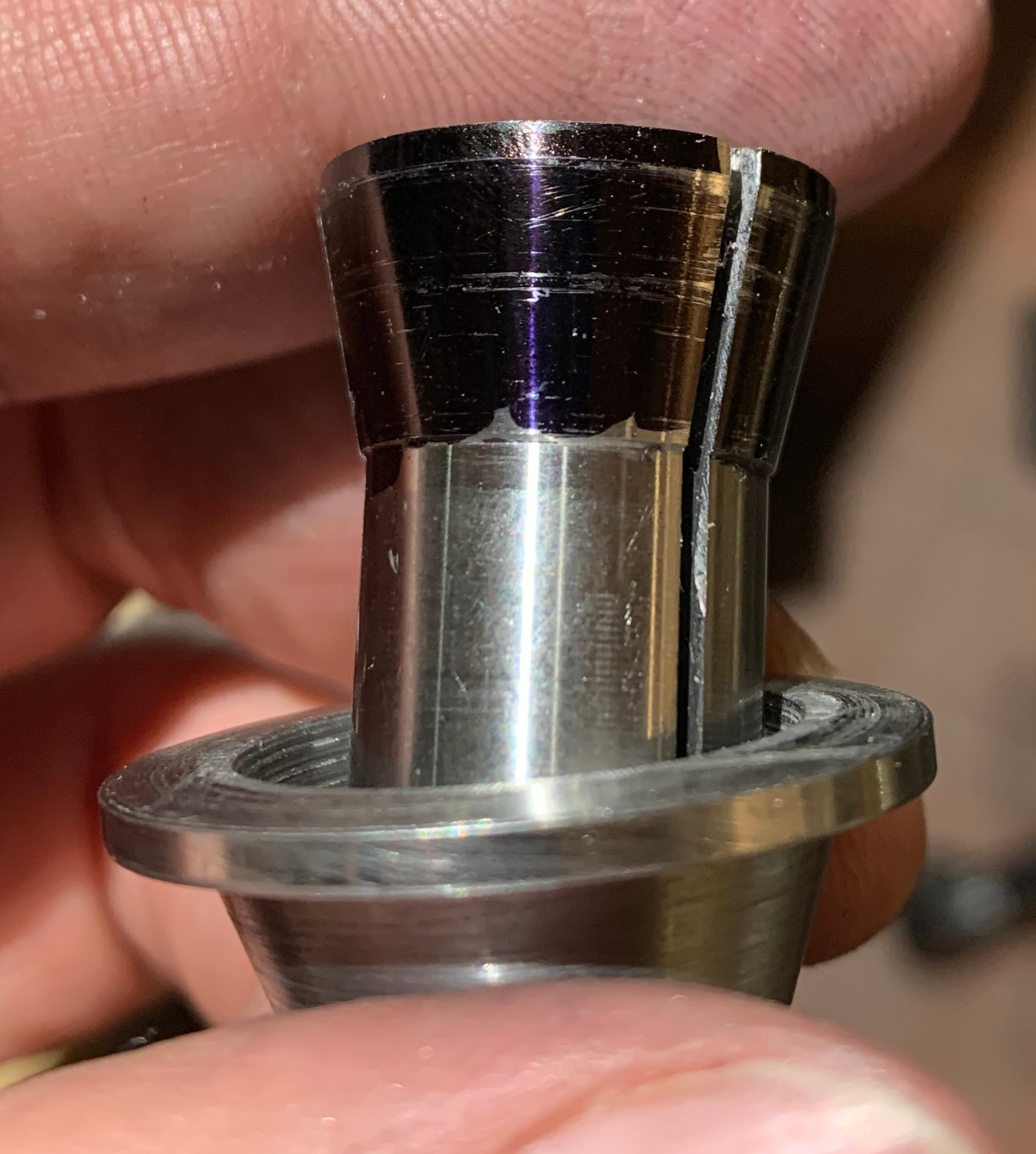
- Grind the OD (check with hi-spot in spindle)
- Install the adapter in the spindle with a tiny amount of Loctite 609 under flange and clamp with the draw bar
- Grind ID in-place
Setting the angle on the compound accurately is my next problem. I decided to do the trig method where you measure the legs of a triangle. The ways are 1 leg and the other leg is perpendicular. I'll move the carriage x along the ways and adjust the compound until the tool post moves by the right amount in y. The tool post will be square to the chuck for this operation. Whatever I use for x, y = x * tan(angle). Tangent isn't too crazy for small angles so I hope this works. Other methods might be more accurate. If I don't get a good print, I may need to use a different method.
For now, I need some carriage stops to control the length of the x leg and I'll use an indicator against the took post to measure the other leg. I was going to buy a carriage stop but one of the first things I saw was this 3-d printed thing and he wanted 45 $ for it. Seems like a lot. Also, this is one of those basic projects that you're meant to do for yourself. So I decided to make a pair.
It's un-filled ABS with a 3/8 hole for drill rod or an indicator and a 1/4-20 clamp for the dovetail. The hinge is integrated into the body. It's 50% filled, which is fairly stout. I bought knobs from McMaster and some "press-fit" threaded inserts. After shipping and the extra parts, it was 42 $ for 2 stops.
BTW, I'm not a fan of the 3-d printing hype and various trinket printing that goes on. If I had a working mill, I would make this out of brass or aluminum and feel smug about it. But for now, the plastic version will have to do. I do not intend to over use the FDM printer (partly due to all the clucking) but I've been surprised at where it can be used effectively. I'm keeping an open mind while simultaneously resisting expectation of The Internet by not printing Groot. if you're quietly thinking about how this could be better done in metal---you're right. And I'll get there someday. Possibly by the end of this build.