[How do I?] Machining Pulley

maker of things

Hermit
Registered
Joined
Jul 23, 2014
Messages
347
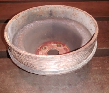
My cousin asked me to make a new pulley for his 4cyl cummins. This is the stock one.
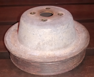
upload_2015-11-5_9-31-22.png

upload_2015-11-5_9-31-53.png
The goal is to make a new one from aluminum that includes accommodation for a second belt to run an accessory. How fussy are the ribs/grooves dimensionally and is there an insert already designed for these belts or would I be best off grinding a hss bit to match the angle?
 
It can be done with regular (60º) thread tool.
Check with your thread gauge
 
Yes the standard 60 degree threading tool will work. Using a pitch gage will tell you how far apart the grooves are. Just divide 1 inch by the number of threads the gage matches to see how far apart the grooves are.
 
My cousin asked me to make a new pulley for his 4cyl cummins. ......
The goal is to make a new one from aluminum that includes accommodation for a second belt to run an accessory. How fussy are the ribs/grooves dimensionally and is there an insert already designed for these belts or would I be best off grinding a hss bit to match the angle?

Rather than reverse engineering the pulley, if you Google "poly vee belt dimensions", you should be able to get the designed profile.

Not wishing to discourage someone from building when you can buy but have you checked to see if there is an OEM or aftermarket adapter that will work? I seem to recall that the way that the auto manufacturers handled this was to make a second pulley that nested inside of the primary pulley which provided for belt driven accessories. If there isn't one available, it may still be easier to make the "add on" pulley for your particular needs.

Bob
 
Looks like a nice project. Concentricity of your part is paramount. Please make sure you are up for the task. Good Luck, Dave.
 
You will just have to check the existing pulley to see if you have a J or K pitch. Then you can get the necessary dimensions from the pdf.
 
I agree with the others.
Work from published data for the belt grooves, not from measurements taken from the pulley itself.
For groove spacing, I would just mount a dial indicator on the lathe bed. Make a list of measurements for each groove, then just cut away. Re-zeroing the indicator between each groove is bad practice (it is probably fine in this application though), because it just creates cumulative error. Zero once on the first groove, then just move the carriage to the next point on the list, very fast and very accurate.

Also, make sure you rough cut as many sides as possible before coming to final dimension. Machining out a large shape like that will reveal every bit of stress in the material. I would true one face, drill and bore the hole undersize. Flip, and grip the bore in the 3jaw, cut the large diameter over size. Grip the outside, hog out the dish. Make sure you take it out of the chuck before you do any more machining so it can find it's new shape, then machine to final sizes. I would probably machine the bore last so I could get the outside centered in the 4jaw.
 
Thanks guys.
Rather than reverse engineering the pulley, if you Google "poly vee belt dimensions", you should be able to get the designed profile.

Not wishing to discourage someone from building when you can buy but have you checked to see if there is an OEM or aftermarket adapter that will work? I seem to recall that the way that the auto manufacturers handled this was to make a second pulley that nested inside of the primary pulley which provided for belt driven accessories. If there isn't one available, it may still be easier to make the "add on" pulley for your particular needs.

Bob
Yea, I offered simpler as a solution, but there is a specific look he is going for, it's kind of a show truck. I'm excited to give this a try. It will for sure be a challenge for my unrefined skills and as Adam Savage says, "failure is always an option".
Looks like a nice project. Concentricity of your part is paramount. Please make sure you are up for the task. Good Luck, Dave.

I'm researching acceptable runout tolerances, for this dia it looks like up to .01" is acceptable. I feel fairly confident I can do better than that.

I agree with the others.
Work from published data for the belt grooves, not from measurements taken from the pulley itself.
For groove spacing, I would just mount a dial indicator on the lathe bed. Make a list of measurements for each groove, then just cut away. Re-zeroing the indicator between each groove is bad practice (it is probably fine in this application though), because it just creates cumulative error. Zero once on the first groove, then just move the carriage to the next point on the list, very fast and very accurate.

Also, make sure you rough cut as many sides as possible before coming to final dimension. Machining out a large shape like that will reveal every bit of stress in the material. I would true one face, drill and bore the hole undersize. Flip, and grip the bore in the 3jaw, cut the large diameter over size. Grip the outside, hog out the dish. Make sure you take it out of the chuck before you do any more machining so it can find it's new shape, then machine to final sizes. I would probably machine the bore last so I could get the outside centered in the 4jaw.
I suspected that the order of operations would be the key.
 
Back
Top