Making a backplate for an ER40 set tru chuck

Thanks to @mmcmdl, I have a P4 blade for the male spindle thread copy. He also has graciously loaned me a Kennametal 3/4" LH threading bar for the internal threads. Much appreciated!
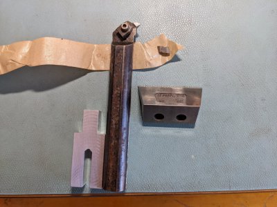
PXL_20220221_174219644.jpg
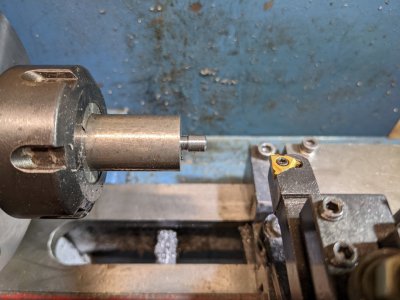
When I get my lathe operational again, I will make the spindle template. Had a gear shaft break this morning. Looks like the shaft fractured in the thread relief. The last couple of days I was having issues with the clip falling off the gear shaft after about 15 minutes of turning. Real annoying. Now I know why it was happening. Have a couple of spares on the way. Parts were cheap, the shipping costs were relatively large compared to the part. $18.50 for parts, $11 for shipping and handling. Minor blip in life.
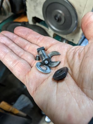
PXL_20220221_164126521.jpg
 
Seems like a long wait (not really, but I am getting impatient) for the gear shaft. So I think I will make one. Not like the one that broke, something simpler, that can get me back in business. All that is really needed is a shaft for the gears that is the correct length. I will use a through M6 bolt to attach it to the gear banjo. If it lasts a couple of weeks, that should be good. No need for a ball oiler for a temporary shaft. I can make this on my mini-lathe.
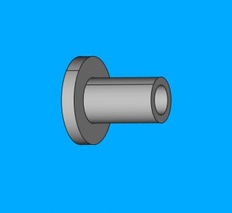
simple_bushing.jpg
19mm at flange, 2mm thick. Body is a hair under 10mm so the gears fit over it. Body length is about 16mm plus a hair. An M6 screw (and washer) will go through the clearance hole to prevent the gear from escaping. Have to make some micrometer measurements and make some minor tweaks, but that's the idea. Might have to make the flange thinner, since the original washer is only 1.6 mm thick. No problem, what's a little tweaking?
 
Last edited:
Hmm, made the gear shaft, but, have to confess, it is a bad design. Why? Because there is no way to lock the shaft position in place. Handling the greasy gears and positioning everything isn't so good. Especially when you realize you forgot the washer on top. When you pull the screw, the tee-nut drops further into the slot. The Grizzly design is better as there is a way to lock the shaft. Back to the drawing board. Gee, by the time I dream this up and make it, the real parts will show up.
 
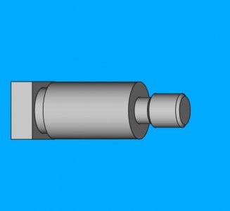
I've concluded that the Grizzly part is a pretty good design and had features that I was not aware of, until I tried to make something better. So I modeled the piece, without the oiler. It is included here. I have the body for the thread and the relief done on the mini-lathe. Got sidetracked on a parting issue which is mostly fixed.
PXL_20220223_225154505.jpggrizzlymodelsansoiler.jpg
Should have it done tomorrow morning. Just thinking about this, I could probably add a ball oiler if I wanted to. I do have some spare ball oilers. Think it is just a couple more holes...
 

Attachments

  • substitute_gearshaft.pdf
    281.9 KB · Views: 1
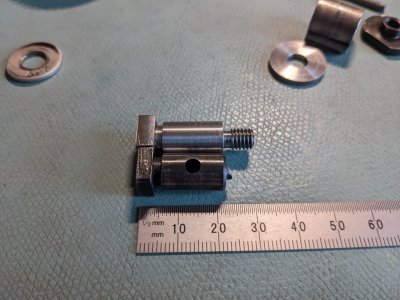
Some final fit up required. The E-clip doesn't quite fit in the slot. I need to make the 8mm diameter section next to the square head about 0.13mm longer! (0.005") Oops. Back on the lathe again to shave a little bit off on the square head side. I know I have a left hand HSS knife edge bit that I ground. Hope it will fit in the gap. Nonetheless, happy with how it is turning out so far. Milled the head to 10mm square using a 10mm collet in a square collet block.
PXL_20220224_193048461.jpg
Kind of far away from making a backplate, I'm afraid, but I need a part like this to have both power feed and threading ability.
 
Well that piece I made above works well enough that even though I have replacement parts from Grizzly, I have no motivation to change it out. Been running it for a week.

Kind of lost my focus on this task. Got sidetracked making a fixture plate for my rotary table. The plate is done, so it is back to the backplate. That means it is time to make the male spindle piece. I had asked a question previously about which faces were the critical ones on the spindle, but this appears to be a low traffic thread - just me talking to myself. BRB while I go ask the question.
 
Got a couple of confusing answers, but, think I know what to do. It has been frustrating in quite a few areas. My power hacksaw is not well. It cut the stock at a pretty severe angle. The cut went towards the saw, so at the top it was true, but by the time it got to the bottom, it had veered 6mm towards the saw frame. Was a new blade, properly tightened. Beautiful smooth cut, but angled a lot. 6mm over 63.5mm or about 5.4 degrees. In the 20 years I've had this, it has never cut like this. Nothing is obviously wrong, but clearly something is. Something is loose, or worn. The gearbox gasket is leaking as well. Been putting off fixing this, but seems like I need to tackle it sometime.

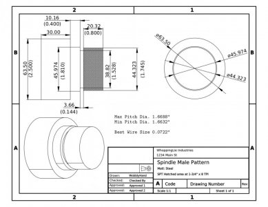
Anyways, took the cut piece of 12L14 to the lathe and started. This is what I am machining to:
spindle_pattern.jpg
Things went ok until I chowdered up the edge of the register. There's enough intact to work, but it is injurious to pride.
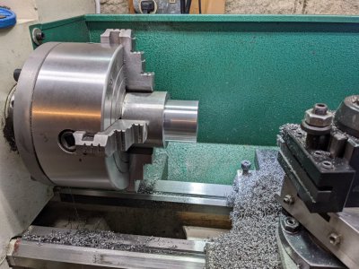
First picture is before effing up. Used a TCMT insert which was pretty good, but nowhere as nice a finish as a TCGT. Used the TCMT because of the interrupted facing cut.
PXL_20220311_223021318.jpg
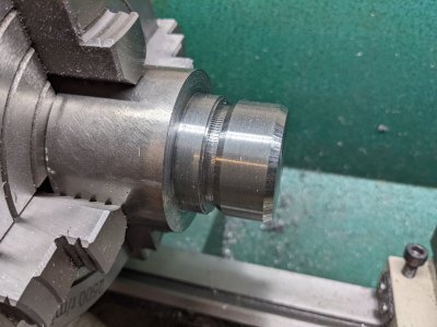
Here's the buggered up register in the next picture. I'm pretty close on dimensions everywhere, so I hope it's savable. Guess I could always flip the piece to get a second chance.
PXL_20220314_173842884.jpg
For some reason, the cross-slide gibs loosened, I think some of the chatter was due to that. And maybe the parting tool wasn't quite at center height. The tilted AXA parting blade holders seem to be harder to adjust than the flat OXA holders. Someday I'll make a rear parting tool.

So now that that is done, I will set up the lathe for 8 TPI threads. Never single pointed 8 TPI before. Earlier, I practiced on 10 TPI, and it seemed ok. Have a P6 blade for my Aloris threading tool that I will try. Also have a P4 blade, which is wider, but I see no need to make it even harder on myself. I'll pull out the threading wires for this, because I want to match the pitch diameters. My bad, I forgot to measure them, so I will have to remove the chuck from the spindle. Hmm, I should remove the chuck first, since I don't want to have to match the start angle of the thread. Next post should be on pitch diameter, or more likely me dropping the wires!
 
Having problems with measuring with the 3 wires. Seem to have consistency issues. 3 measurements, 3 different readings differing by over 0.001. Each repeated measurement got smaller, However, they all say the existing spindle pitch diameter is right at the lowest limit for a 2A thread. I got a measurement of 1.7676" using 0.0718" wires. Two of the wires were 0.07175" and one was 0.07185". So, roughly the pitch diameter is 1.6605".
 
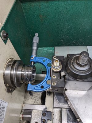
Made a McGiver contraption to get a little more consistency. Works better than expected. Clamped a mic in a toolholder, so it would be consistently positioned. Repeatability is within tenths now, not thousandth. Measured using the 1 wire method this time to reduce the fiddle factor.

PD = 2T - D - k, where T is a 1 wire measurement, D is a diameter measurement, and k is a constant.
k is given by: k = 3W - 0.86603*pitch.

For my (single) wire diameter of 0.0718", and a pitch of 0.125", (8 TPI) k = 0.1071.
My measurements were: T = 1.7532", D = 1.7390". Therefore PD = 2*1.7532 - 1.7390 - 0.1071 = 1.6603"
Happy enough to install the chuck again, change the gears and single point some threads.
PXL_20220314_203702199.jpg
 
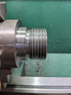
It's not pretty, but the spindle copy, and I use that term loosely, is done! Matched the thread diameter pretty well, and am within +0.003 of the pitch diameter. Afraid of mucking it up at this point. Did a test of a couple of backplates that I have, a spare backplate, and a backplate that has my 5" chuck mounted. Spun on easily like the real spindle, and locked up against the register. I could clean up the register face with a knife edge, but once again, think it is good enough.
PXL_20220315_152743960.jpg
Threads were cut at 90 RPM using HSS. Stalled the lathe once, apparently taking too deep of a cut. Broke the chip and backed it off by half the cut and it was fine. Took a couple of passes to get rid of all the stall damage. Fortunately this was at the beginning of the single pointing process. At 90 RPM there was no problem stopping in time. What also helped was the 30 degree angle that I had put in next to the thread relief. Made it a lot easier to detect when the point had finished cutting.

Was half debating whether or not to bore out the center. It would make it lighter, but it would "ruin" the stock, should I decide to repurpose it. For now I will leave it solid.
 
Back
Top