-
Welcome back Guest! Did you know you can mentor other members here at H-M? If not, please check out our Relaunch of Hobby Machinist Mentoring Program!
You are using an out of date browser. It may not display this or other websites correctly.
You should upgrade or use an alternative browser.
You should upgrade or use an alternative browser.
Mike's 6-Axis Articulated Robot
- Thread starter macardoso
- Start date
- Joined
- Mar 26, 2018
- Messages
- 2,724
Well, this weekend was wildly successful with regards to the robot. Will likely require several posts to share everything so here we go.
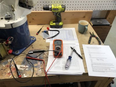
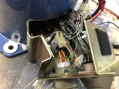
I spent a chunk of Saturday afternoon working through the checklist I posted previously. A good chunk of the time was spent verifying the pinouts of all the cables and connectors against checklist in the robot service manual. I figured a few hours on this task would be well worth it versus burning out a motor thanks to some hacky wiring on my end.
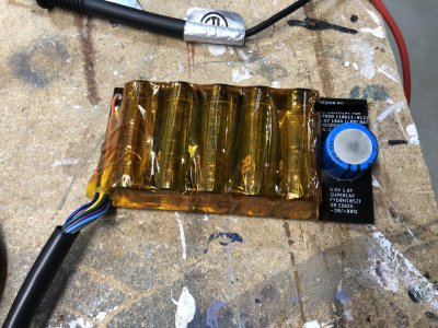
Next up was to solder up the encoder backup battery board. This required some soldering of the lithium primary batteries and the 5V super capacitor. I didn't think much of this at first, other than knowing I needed to be careful of heat management during soldering. I soldered the capacitor first and then added the batteries one by one. I kept the soldering iron at max temp so I could melt the solder very quickly and move on. This is a trick I learned to minimize the total heat transfer into components. Better to be hot and fast than pretty hot and slow to melt. As I finished getting all the batteries on the board, I took a voltage measurement and only got 0.24VDC (should have been 3.68V). Exactly at that moment I also noticed the first couple batteries were getting hot! Something was shorting out and it made no sense to me at all! I ran outside with the battery in a panic waiting for it to burst into flames, then changed my mind and decided I wanted to try to save the $50 in batteries. So I ran downstairs and did a emergency desolder of the batteries. Thankfully everything cooled down.
I took two hours cleaning the board and investigating why it started to melt down. I still don't have a good answer to be honest, but maybe some excess solder got between the positive tab on the battery and the case (which is also the negative terminal). I eventually reassembled the board without changing anything and it was OK. The plastic wrapper on the batteries got pretty messed up from getting splashed with molten solder during my rushed desoldering job, so they were all individually wrapped in kapton tape, then once I confirmed the battery pack was working as expected, the whole pack got wrapped as well. Not pretty, but it is working.
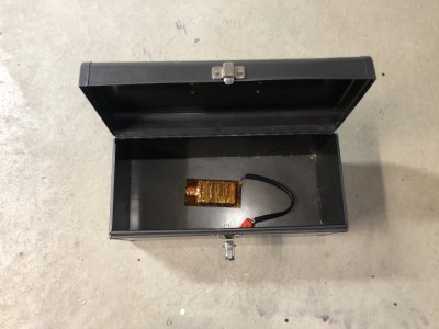
It spent two hours in a tool box to make sure it did not combust. I also triple checked the connections and polarity. Final voltage was 3.68VDC.
A careful check of the input power connections left me as confident as I could be in the installation. I am getting about 215VAC unloaded out of the transformer sled. I expect this will drop a bit once the robot is pulling some load on it.
I sat on the phone with my dad as I went through literally every item I could think of going wrong with powering this on, and what I had done to ensure it would be OK. Finally said a little prayer and flipped the switch!
No boom! No smoke! The pilot light came to life, the fans kicked on, the teach pendant made two little chirps and displayed the most wonderful welcome screen, "T-PENDANT Ready".
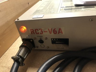
I really had no idea whatsoever at this point if this would turn on at all. The fact that it just started up without a fuss was wonderful. I think it was last powered on in 2011, and had spent a fair bit of time in the cold, damp warehouse of HGR industrial surplus.
To be continued...
I spent a chunk of Saturday afternoon working through the checklist I posted previously. A good chunk of the time was spent verifying the pinouts of all the cables and connectors against checklist in the robot service manual. I figured a few hours on this task would be well worth it versus burning out a motor thanks to some hacky wiring on my end.


Next up was to solder up the encoder backup battery board. This required some soldering of the lithium primary batteries and the 5V super capacitor. I didn't think much of this at first, other than knowing I needed to be careful of heat management during soldering. I soldered the capacitor first and then added the batteries one by one. I kept the soldering iron at max temp so I could melt the solder very quickly and move on. This is a trick I learned to minimize the total heat transfer into components. Better to be hot and fast than pretty hot and slow to melt. As I finished getting all the batteries on the board, I took a voltage measurement and only got 0.24VDC (should have been 3.68V). Exactly at that moment I also noticed the first couple batteries were getting hot! Something was shorting out and it made no sense to me at all! I ran outside with the battery in a panic waiting for it to burst into flames, then changed my mind and decided I wanted to try to save the $50 in batteries. So I ran downstairs and did a emergency desolder of the batteries. Thankfully everything cooled down.
I took two hours cleaning the board and investigating why it started to melt down. I still don't have a good answer to be honest, but maybe some excess solder got between the positive tab on the battery and the case (which is also the negative terminal). I eventually reassembled the board without changing anything and it was OK. The plastic wrapper on the batteries got pretty messed up from getting splashed with molten solder during my rushed desoldering job, so they were all individually wrapped in kapton tape, then once I confirmed the battery pack was working as expected, the whole pack got wrapped as well. Not pretty, but it is working.

It spent two hours in a tool box to make sure it did not combust. I also triple checked the connections and polarity. Final voltage was 3.68VDC.

A careful check of the input power connections left me as confident as I could be in the installation. I am getting about 215VAC unloaded out of the transformer sled. I expect this will drop a bit once the robot is pulling some load on it.
I sat on the phone with my dad as I went through literally every item I could think of going wrong with powering this on, and what I had done to ensure it would be OK. Finally said a little prayer and flipped the switch!
No boom! No smoke! The pilot light came to life, the fans kicked on, the teach pendant made two little chirps and displayed the most wonderful welcome screen, "T-PENDANT Ready".

I really had no idea whatsoever at this point if this would turn on at all. The fact that it just started up without a fuss was wonderful. I think it was last powered on in 2011, and had spent a fair bit of time in the cold, damp warehouse of HGR industrial surplus.
To be continued...
- Joined
- Mar 26, 2018
- Messages
- 2,724
So at this point I was ecstatic. I knew if I could get this far, then there was a much better chance that things were in better shape than I had worried they might be in. After power up, I was immediately greeted with some error codes. The teach pendant display is just a two line LCD display, so the information it provides is pretty minimal.
The first error I got was ERROR 771. The user manual had this explanation:

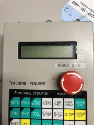
From my experience earlier working with the encoders on my bench, I know the encoder sets all status flags (including the overspeed flag) after the external backup battery source is disconnected. Since this robot had been without battery for the encoders all these years, this made sense to me. I jumped right into the encoder reset procedure in the manual.
Each motor, under the plastic covers, has a 2 pin red plastic connector coming off of the encoder connector. If a shorting jumper is installed in this location, 5V is applied to the encoder reset pin. Holding this condition after power on for 4 seconds clears all the errors and resets the multi-turn counter on the encoder. This was done one encoder at a time, starting with J1 and working my way up to J6. After each reset, the teach pendant would display a new error code, first ERROR 772, then 773, and finally 776.
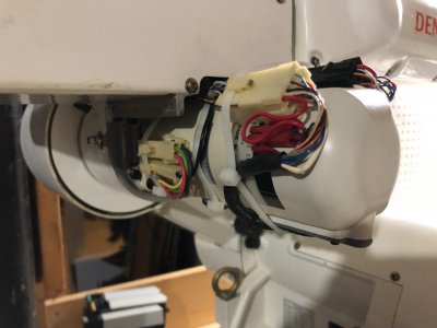
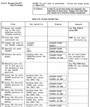
This was completed without issue. I'm so grateful to Denso for providing the old manuals for this robot! I don't think I could have figured any of this out without them. Next was the CALSET procedure. This requires you to place the robot into a known configuration against the hard stops and run a procedure which the controller uses to learn the encoder positions at the ends of travel and relate them to the RANG calibration values which I'll explain in a minute.
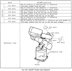
The manual is pretty clear about the procedure, however whenever I got to step 5, I would get an ERROR 8 and the CALSET would terminate. It took me a minute to figure this out since ERROR 8 was an active ESTOP circuit, and I was able to verify all my circuits were closed and working properly.
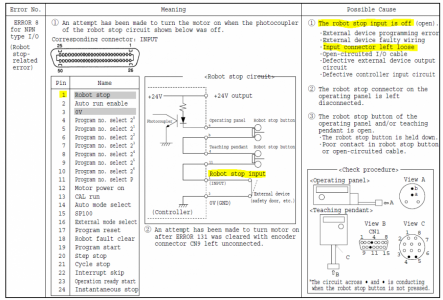
Eventually I found the service manual has a chapter titled "Descriptions of Major Error Codes". In here, there was a mention to a function which is not clearly described in the user manual. Apparently the INPUT cable is not an optional component, and it has several signals which are needed to perform standard operations on the robot. Specifically in this case, the INPUT cable is part of the ESTOP circuit and needs a connection between pins 1 and 3. I had left these "optional" external interface cables disconnected during startup. I soldered the two tiny 28 AWG wires together and wrapped them in electrical tape. From there, I could complete the CALSET operation without any fuss.
I'll add at this point that the functions on the teach pendant are not very intuitive. Most keys have 2-3 functions which need to be selected using the shift key. The manual lacks a comprehensive description of all the functions on the teach pendant, so much of my knowledge of navigating the options has come from copying some example procedures from various parts of the manual and trying to modify what they are doing to my needs. In most cases, either nothing happens or it will throw an error code at me.
With CALSET done, I needed to go in and verify the 18 critical parameters for robot operation were loaded properly. These are PLIM (positive software joint angle limit), NLIM (negative software joint angle limit), and RANG (robot calibration data). Using a procedure from the manual, I was able to read all these values and set some of the PLIM and NLIM values back to default. These might be changed by an end user to make sure the robot can't run into an obstacle that is in its workspace (like a wall). The RANG values are unique numbers for each joint that are measured carefully at the factory when it was built. They represent the angle in degrees of the joint when it is pressed against the hard stop. The values are measured down to 3 or 4 decimal places. The robot combines these values, along with the encoder data saved during CALSET to perform the kinematic equations and locate the robot in 3D space. If these values (printed on a sticker on the robot itself) were to be lost, the robot would be nearly inoperable and could not properly perform any cartesian motion. Similarly, if the hardstops were to be moved, the same issue would occur. The RANG values in the controller matched those printed on the robot which confirms that this was the control box paired with this exact robot when it was running, and that it wasn't mistakenly swapped after it was discarded. That is a big issue with buying used robots.
After I got these done, the robot was clear of errors other than a RECPLACE BATT. message that would show up each time I turned the controller on. This is a preventative maintenance message that is based on the elapsed time since battery replacement (in my case, 9 years overdue), but is not an actual error message indicating low battery or depleted battery. When the connectors come for the controller battery, I will replace it.
Pressing the MOTOR ON button gave a resounding click of a contactor inside the controller pulling in, a relay in the controller clicking on, and the two brakes of the J2 and J3 motors releasing. The motors hummed to life with they typical whining of AC servo motors as the PWM voltage runs through the windings. I messed around with trying to move the motors but couldn't get anywhere. First thing I learned was that the deadman switch needed to be held to get it to do anything. Once I was holding that and pressed the jog button for J1, I was greeted with an ERROR 4 message. The manual explained that once per power on, the calibration operation needs to be run. This slightly bumps each motor forward and backward. This comes from a limitation in the Tamagawa encoders where full resolution is not available until the motor shaft has been moved 2 mechanical degrees after power on. Once each motor is moved slightly, the encoder resolution is increased x64.

At this point, I cleared the error, pressed [CAL] and [ENT] on the teach pendant. The motors hummed a little (the motion after the gearbox reduction is imperceptible) and the teach pendant displayed CAL OK. I tried moving the joint motors again and got no motion and no errors. From reading the manual earlier I remembered something about the robot starting up at 0% speed as a safety precaution. I found this section in the manual and entered [SP] and [100] on the teach pendant followed by [ENT]. The robot confirmed the speed was set to 10%. Any time the teach pendant is in MANUAL mode (rather than AUTO) the speed is multiplied by 10% for safety (and 5% if in TEACH CHECK) which in this case brought the speed down to 1% of maximum. From there I was able to hold the deadman switch and press J1+ and the joint started to move!
EDIT: Everything went well at this point up until jogging J4. It would only move in one direction and error on overtravel in the other no matter where is was positioned. Turns out that the CALSET procedure has some contradictory information between the image, text description, and CALSET procedure steps. I had done the CALSET against the wrong hard stop. Once corrected, the joints moved correctly.
To be continued!
The first error I got was ERROR 771. The user manual had this explanation:


From my experience earlier working with the encoders on my bench, I know the encoder sets all status flags (including the overspeed flag) after the external backup battery source is disconnected. Since this robot had been without battery for the encoders all these years, this made sense to me. I jumped right into the encoder reset procedure in the manual.
Each motor, under the plastic covers, has a 2 pin red plastic connector coming off of the encoder connector. If a shorting jumper is installed in this location, 5V is applied to the encoder reset pin. Holding this condition after power on for 4 seconds clears all the errors and resets the multi-turn counter on the encoder. This was done one encoder at a time, starting with J1 and working my way up to J6. After each reset, the teach pendant would display a new error code, first ERROR 772, then 773, and finally 776.

This was completed without issue. I'm so grateful to Denso for providing the old manuals for this robot! I don't think I could have figured any of this out without them. Next was the CALSET procedure. This requires you to place the robot into a known configuration against the hard stops and run a procedure which the controller uses to learn the encoder positions at the ends of travel and relate them to the RANG calibration values which I'll explain in a minute.

The manual is pretty clear about the procedure, however whenever I got to step 5, I would get an ERROR 8 and the CALSET would terminate. It took me a minute to figure this out since ERROR 8 was an active ESTOP circuit, and I was able to verify all my circuits were closed and working properly.

Eventually I found the service manual has a chapter titled "Descriptions of Major Error Codes". In here, there was a mention to a function which is not clearly described in the user manual. Apparently the INPUT cable is not an optional component, and it has several signals which are needed to perform standard operations on the robot. Specifically in this case, the INPUT cable is part of the ESTOP circuit and needs a connection between pins 1 and 3. I had left these "optional" external interface cables disconnected during startup. I soldered the two tiny 28 AWG wires together and wrapped them in electrical tape. From there, I could complete the CALSET operation without any fuss.

I'll add at this point that the functions on the teach pendant are not very intuitive. Most keys have 2-3 functions which need to be selected using the shift key. The manual lacks a comprehensive description of all the functions on the teach pendant, so much of my knowledge of navigating the options has come from copying some example procedures from various parts of the manual and trying to modify what they are doing to my needs. In most cases, either nothing happens or it will throw an error code at me.
With CALSET done, I needed to go in and verify the 18 critical parameters for robot operation were loaded properly. These are PLIM (positive software joint angle limit), NLIM (negative software joint angle limit), and RANG (robot calibration data). Using a procedure from the manual, I was able to read all these values and set some of the PLIM and NLIM values back to default. These might be changed by an end user to make sure the robot can't run into an obstacle that is in its workspace (like a wall). The RANG values are unique numbers for each joint that are measured carefully at the factory when it was built. They represent the angle in degrees of the joint when it is pressed against the hard stop. The values are measured down to 3 or 4 decimal places. The robot combines these values, along with the encoder data saved during CALSET to perform the kinematic equations and locate the robot in 3D space. If these values (printed on a sticker on the robot itself) were to be lost, the robot would be nearly inoperable and could not properly perform any cartesian motion. Similarly, if the hardstops were to be moved, the same issue would occur. The RANG values in the controller matched those printed on the robot which confirms that this was the control box paired with this exact robot when it was running, and that it wasn't mistakenly swapped after it was discarded. That is a big issue with buying used robots.
After I got these done, the robot was clear of errors other than a RECPLACE BATT. message that would show up each time I turned the controller on. This is a preventative maintenance message that is based on the elapsed time since battery replacement (in my case, 9 years overdue), but is not an actual error message indicating low battery or depleted battery. When the connectors come for the controller battery, I will replace it.
Pressing the MOTOR ON button gave a resounding click of a contactor inside the controller pulling in, a relay in the controller clicking on, and the two brakes of the J2 and J3 motors releasing. The motors hummed to life with they typical whining of AC servo motors as the PWM voltage runs through the windings. I messed around with trying to move the motors but couldn't get anywhere. First thing I learned was that the deadman switch needed to be held to get it to do anything. Once I was holding that and pressed the jog button for J1, I was greeted with an ERROR 4 message. The manual explained that once per power on, the calibration operation needs to be run. This slightly bumps each motor forward and backward. This comes from a limitation in the Tamagawa encoders where full resolution is not available until the motor shaft has been moved 2 mechanical degrees after power on. Once each motor is moved slightly, the encoder resolution is increased x64.

At this point, I cleared the error, pressed [CAL] and [ENT] on the teach pendant. The motors hummed a little (the motion after the gearbox reduction is imperceptible) and the teach pendant displayed CAL OK. I tried moving the joint motors again and got no motion and no errors. From reading the manual earlier I remembered something about the robot starting up at 0% speed as a safety precaution. I found this section in the manual and entered [SP] and [100] on the teach pendant followed by [ENT]. The robot confirmed the speed was set to 10%. Any time the teach pendant is in MANUAL mode (rather than AUTO) the speed is multiplied by 10% for safety (and 5% if in TEACH CHECK) which in this case brought the speed down to 1% of maximum. From there I was able to hold the deadman switch and press J1+ and the joint started to move!
EDIT: Everything went well at this point up until jogging J4. It would only move in one direction and error on overtravel in the other no matter where is was positioned. Turns out that the CALSET procedure has some contradictory information between the image, text description, and CALSET procedure steps. I had done the CALSET against the wrong hard stop. Once corrected, the joints moved correctly.
To be continued!
Last edited:
- Joined
- Mar 26, 2018
- Messages
- 2,724
I quickly gained confidence and was jogging the robot at SP 100 (100% speed, times 10% during tech pendant operations). The robots software continuously monitors the position and will stop you with an ERROR whenever you exceed some limit (either joint angle, joint speed, or cartesian mathematical limit). This lets you move it around with reckless abandon (just kidding). But it is nice that you can't overtravel the robot and if you hit one of these limits, you just need to let go of the jog button, press [C] on the teach pendant to clear the error, and jog away in an unrestricted direction.
Here are the very first joint moves, running at 10% of maximum speed.
After gaining confidence with the joint moves, I placed the teach pendant in XY cartesian mode by pressing the [X-Y] button. This changes the jog buttons from moving each joint to moving the robot in XYZ space relative to the global world coordinate frame (X = forward and backward, Y = side to side, Z = up away from the table). Rotations about these "cardinal" axes are also permissible.
Thanks to singularities, the robot cannot be jogged quite as easily in this mode. The joints cannot flip (e.g. wrist down to wrist up) like they can in joint mode, and motion near singularities results in errors as the robot pre-calculates that a joint will need to rotate extremely fast. This is nice that the robot is able to halt motion before the motor takes off. It seems hard to command the robot to do anything wrong, short of running it into an obstacle.
Here is a video of cartesian moves at 10% speed in a "normal" arm-forward, wrist-down configuration.
Rotations in cartesian mode are wicked cool. The position of the tool (in this case, the center point of the face of the tool body platter) is held fixed in 3D space, while the platter is rotated about the cardinal axes. Same configuration at 10% speed.
Finally, I placed the robot in tool frame cartesian mode. This is similar to normal cartesian mode except all the motions are relative to the moving coordinate frame attached to the tool. In X-Y cartesian mode, jogging in the Z- direction moves the tool down towards the table, in TOOL cartesian mode, jogging in Z- direction moves the tool forward along whatever vector it is currently pointing. This would make programming a gripper much easier, especially if what it needed to grab was not aligned with the global cartesian coordinate frame.
This video was aimed at aligning the robot with the camera in the Z axis and performing translations and rotations in the TOOL frame cartesian space. Same configuration as above at 10% speed.
- Joined
- Mar 26, 2018
- Messages
- 2,724
As an aside the robot's motion in some places is not as smooth as I would have hoped. The motion gets slightly jerky with an amplitude of maybe 1/16". I have a feeling this is an issue with the J2 gearbox. This was the one which I could not remove during cleaning and was absolutely filthy with grit and grime. I flushed it with oil, but I think it is time I go back and try harder to pull the flex spline cup and give it a good cleaning and greasing. I can hear some grinding and crunching sounds as the robot moves and these seem correlated with the jerky motion.
Probably related, I was able to use the teach pendant to pull the diagnostics out of the robot. The current run time (with motors on) is 27268 hours. This is roughly 13 years of 40 hour work weeks! She is an old girl!
Hoping a good cleaning and greasing is all that is needed to get it running better. I'm sure the entire robot has a whole lot more slop than a new unit as the gearboxes wear, but it will be perfect for messing around with at home.
- Joined
- Mar 26, 2018
- Messages
- 2,724
I could sit around and play with this thing in jog mode all day, but I started looking into writing programs. Again, I feel like a grandpa trying to navigate an iPhone, but I'm slowly picking up on how to get through the menus.
The robot needs to be in [MANUAL] mode to work with programs. Clicking [PRO] with allow you to enter the program number (e.g. [1]) and hitting [ENT] will open the program and display the title "PROGRAM 1". Clicking the [FWD] and [BACK] keys will scroll through the program steps.
Using the diagnostics functions on the teach pendant, I was able to see that the previous owner's programs were still loaded and were using 278/8000 program steps (also used by general purpose integer and floating point variables) and 562/1200 points (positions saved in joint/cartesian space).
Here is the full program 1 saved in the controller from the previous owner. No idea what it does yet.
EDIT: Added comments to each line using the comment character "//" (not supported within robot). Added description of each function from the programming manual.
The robot needs to be in [MANUAL] mode to work with programs. Clicking [PRO] with allow you to enter the program number (e.g. [1]) and hitting [ENT] will open the program and display the title "PROGRAM 1". Clicking the [FWD] and [BACK] keys will scroll through the program steps.
Using the diagnostics functions on the teach pendant, I was able to see that the previous owner's programs were still loaded and were using 278/8000 program steps (also used by general purpose integer and floating point variables) and 562/1200 points (positions saved in joint/cartesian space).
Here is the full program 1 saved in the controller from the previous owner. No idea what it does yet.
C++:
PROGRAM 1
0010 SUB1
0020 ACP A002
=  $      GO1
0030 SUB1
0040 MVS P,P0001
0050 LABL 1
0060 ISP 60
0070 ACC 20
0080 JI 3-2
0090 JMP 3
0100 LABL 2
0110 APR E
APR=80.0
0120 MVS E,P0021
0130 MVS E,P0022
0140 ISP 4
0150 E_MUL
0160 MVR P0001
     P0023,P0024
0170 ARV 5
0180 ON 1
0190 E_MULEND
0200 ISP 10
0210 MVR P
     P0025,P0026
0220 MVR P
     P0027,P0028
0230 ISP 3
0240 MVR P
     P0029,P0030
0250 ISP 10
0260 MVR P
     P0031,P0032
0270 MR E
     P0033,P0034
0280 OFF 1
0290 ISP 60
0300 DEP E
DEP=80.0
0310 SUB 1
0320 SUB 2
0330 JMP 5
0340 LABL 3
0350 JI 4-4
0360 JMP 5
0370 LABL 4
0380 ISP 60
0390 APR E
APR=80.0
0400 MVS E, P0041
0410 MVS E, P0042
0420 ISP 4
0430 E_MUL
0440 MVR P
     P0043,P0044
0450 ARV 5
0460 ON 1
0470 E_MULEND
0480 ISP 10
0490 MVR P
     P0045,P0046
0500 MVR P
     P0047,P0048
0510 ISP 3
0520 MVR P
     P0049,P0050
0530 ISP 10
0540 MVR P
     P0051,P0052
0550 MVR E
     P0053,P0054
0560 OFF 1
0570 ISP 60
0580 DEP E
DEP=80.0
0590 SUB 1
0600 SUB 3
0610 LABL 5
0620 ISP 60
0630 ACC 20
0640 END
EDIT: Added comments to each line using the comment character "//" (not supported within robot). Added description of each function from the programming manual.
C++:
PROGRAM 1
0010 SUB1    //SUBROUTINE 1 CALL
0020 ACP A002    //9.5X NEW FEATURE, AREA COMPARE
=  $      GO1    //COMPARE CURRENT POSITION ($) TO THE AREA VARIABLE A002. IF WITHIN (=) GO TO LABEL 1
0030 SUB1    //SUBROUTINE 1 CALL
0040 MVS P,P0001
0050 LABL 1    //JUMP DESTINATION LABEL 1
0060 ISP 60    //SET SPEED 60%
0070 ACC 20    //SET ACCELERATION 20%
0080 JI 3-2    //JUMP TO LABEL 3 WHEN INPUT 2 IS ON
0090 JMP 3    //JUMP TO LABEL 3
0100 LABL 2    //JUMP DESTINATION LABEL 2
0110 APR E    //APPROACH WITH EXACT STOP, 80 MM
APR=80.0
0120 MVS E,P0021    //LINEAR CP MOVE WITH EXACT STOP, POSITION 0021
0130 MVS E,P0022    //LINEAR CP MOVE WITH EXACT STOP, POSITION 0021
0140 ISP 4    //SET SPEED 4%
0150 E_MUL    //EASY MULTI-TASK (EM MODE) DECLARATION, USED FOR ARV COMMAND
0160 MVR P    //ARC INTERPOLATION CP MOVE, CONSTANT VELOCITY PASS MOVEMENT
     P0023,P0024
0170 ARV 5    //9.5X NEW FEATURE, WAIT FOR PREVIOUS MOTION COMMAND TO REACH 5% COMPLETE BEFORE EXECUTING NEXT COMMAND
0180 ON 1    //OUTPUT 1 ON, TURNS ON @ 5% OF PREVIOUS MVR COMMAND COMPLETION
0190 E_MULEND    //EASY MULTI-TASK (EM MODE) END DECLARATION
0200 ISP 10
0210 MVR P    //ARC INTERPOLATION CP MOVE, CONSTANT VELOCITY PASS MOVEMENT
     P0025,P0026
0220 MVR P    //ARC INTERPOLATION CP MOVE, CONSTANT VELOCITY PASS MOVEMENT
     P0027,P0028
0230 ISP 3
0240 MVR P    //ARC INTERPOLATION CP MOVE, CONSTANT VELOCITY PASS MOVEMENT
     P0029,P0030
0250 ISP 10    //SET SPEED 10%
0260 MVR P    //ARC INTERPOLATION CP MOVE, CONSTANT VELOCITY PASS MOVEMENT
     P0031,P0032
0270 MVR E    //ARC INTERPOLATION CP MOVE, EXACT STOP
     P0033,P0034
0280 OFF 1    //OUTPUT 1 OFF
0290 ISP 60    //SET SPEED 60%
0300 DEP E    //DEPART WITH EXACT STOP, 80 MM
DEP=80.0
0310 SUB 1    //SUBROUTINE 1 CALL
0320 SUB 2    //SUBROUTINE 2 CALL
0330 JMP 5    //JUMP TO LABEL 5
0340 LABL 3    //JUMP DESTINATION LABEL 3
0350 JI 4-4    //JUMP TO LABEL 3 WHEN INPUT 4 IS ON
0360 JMP 5    //JUMP TO LABEL 5
0370 LABL 4    //JUMP DESTINATION LABEL 4
0380 ISP 60    //SET SPEED 60%
0390 APR E    //APPROACH WITH EXACT STOP, 80 MM
APR=80.0
0400 MVS E, P0041    //LINEAR CP MOVE WITH EXACT STOP, POSITION 0041
0410 MVS E, P0042    //LINEAR CP MOVE WITH EXACT STOP, POSITION 0042
0420 ISP 4    //SET SPEED 4%
0430 E_MUL    //EASY MULTI-TASK (EM MODE) DECLARATION, USED FOR ARV COMMAND
0440 MVR P    //ARC INTERPOLATION CP MOVE, CONSTANT VELOCITY PASS MOVEMENT
     P0043,P0044
0450 ARV 5    //9.5X NEW FEATURE, WAIT FOR PREVIOUS MOTION COMMAND TO REACH 5% COMPLETE BEFORE EXECUTING NEXT COMMAND
0460 ON 1    //OUTPUT 1 ON, TURNS ON @ 5% OF PREVIOUS MVR COMMAND COMPLETION
0470 E_MULEND    //EASY MULTI-TASK (EM MODE) END DECLARATION
0480 ISP 10
0490 MVR P    //ARC INTERPOLATION CP MOVE, CONSTANT VELOCITY PASS MOVEMENT
     P0045,P0046
0500 MVR P    //ARC INTERPOLATION CP MOVE, CONSTANT VELOCITY PASS MOVEMENT
     P0047,P0048
0510 ISP 3    //SET SPEED 3%
0520 MVR P    //ARC INTERPOLATION CP MOVE, CONSTANT VELOCITY PASS MOVEMENT
     P0049,P0050
0530 ISP 10    //SET SPEED 10%
0540 MVR P    //ARC INTERPOLATION CP MOVE, CONSTANT VELOCITY PASS MOVEMENT
     P0051,P0052
0550 MVR E     //ARC INTERPOLATION CP MOVE, EXACT STOP
     P0053,P0054
0560 OFF 1    //OUTPUT 1 OFF
0570 ISP 60    //SET SPEED 60%
0580 DEP E    //DEPART WITH EXACT STOP, 80 MM
DEP=80.0
0590 SUB 1    //SUBROUTINE 1 CALL
0600 SUB 3    //SUBROUTINE 3 CALL
0610 LABL 5    //JUMP DESTINATION LABEL 5
0620 ISP 60    //SET SPEED 60%
0630 ACC 20    //SET ACCELERATION 20%
0640 END    //END OF PROGRAM
Last edited:
- Joined
- Mar 26, 2018
- Messages
- 2,724
Wrote a basic positioning program and was able to verify using Teach Check. Quickly wired up a switch for AUTO ENABLE on input pin 2. This is needed to switch the robot from MANUAL or TEACH CHECK to AUTO. No pictures because the wiring is ugly and I was excited to see this thing run!
AUTO runs the program as written at full speed.
Here is my simple program at 50% speed.
And here at full speed. Maybe not quite as fast as some of the most modern robots at trade shows, but it is scary fast when you are watching it in person!
AUTO runs the program as written at full speed.
Here is my simple program at 50% speed.
And here at full speed. Maybe not quite as fast as some of the most modern robots at trade shows, but it is scary fast when you are watching it in person!

