Mike's CNC G0704 - Block 4 Upgrades

macardoso

H-M Supporter - Silver Member
Joined
Mar 26, 2018
Messages
2,724
Hi all,

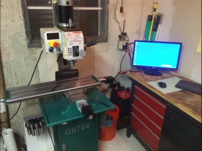
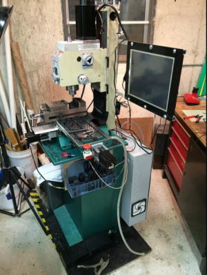
I originally purchased and converted my G0704 mill to CNC back in the 2012-2013 timeframe. This little machine has become the backbone of my shop capabilities for the past decade or so. It has gone through roughly 3 previous generations of conversions, with significant changes in capabilities at each. Roughly speaking, the progression looked like this:

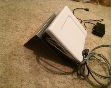
Block 1: Basic Hoss Machine (Hoss2006) conversion
  • Roton ballscrews
  • Stock spindle
  • 4 axis stepper motor control
  • Mach 3
1682685473253.png
1682685053657.png

Block 2: Improved control panel
  • Ethernet Smoothstepper & CNC4PC breakout boards
  • Limit switches
  • DMM Technology 750W AC servo belt drive spindle
  • Touch screen for Mach 3
1682685078310.png
1682685491003.png

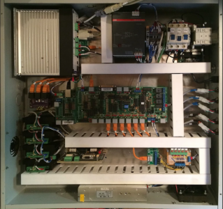
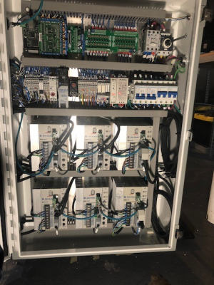
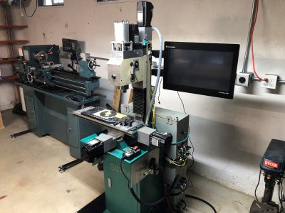
Block 3: Advanced Control Panel & AC Servo Conversion
  • Mach 4 & Ethernet Smoothstepper
  • 750W Allen Bradley Ultra 3000 & MPL AC servos on X and Y, 1800W on Z
  • 1800W AC Servo Spindle, 5000 rpm belt drive
  • Pneumatic Drawbar for Tormach TTS tooling
  • True closed-loop rigid tapping & gear hobbing
  • Cable management
  • MPG Pendant
  • LUA scripting for feedback data from servo drives (e.g., spindle load meter)
  • Absolute homing from servo absolute encoders
  • Probing
1682685892626.png
Image029.jpg

Block 4: Mechanical Accuracy and Ease of Use Improvements TBD...

Beyond the spindle belt drive conversion and motor mounts, the mechanics of this machine remain more or less unchanged from the purchase of this machine. Prior upgrades have been focused on electrical controls improvements. For the most part, I am completely happy with where the control stands today and will likely not be making any substantial changes to this part. I'll follow this post up with my roadmap for improvements.

I am a new dad, so free time is a lot less than it used to be. I'll be plugging away at this as I have time.

This thread is a continuation of a previous one on this machine, link is below.

 
Last edited:
Here are the changes I am hoping to accomplish. I've sorted them into two categories: the Must Haves and the Wish List.

The Must Haves
  • 10k RPM Spindle Pulley Swap
  • Measurement of starting point for machine accuracy (DONE)
    • Backlash
    • Axis orthogonality
    • Spindle tram
    • Movement Accuracy
  • Quick pass at hand scraping
    • Scraping of ways for improved fit
    • Scraping of gibs for improved fit
    • Scraping of column/base interface to correct column alignment
    • Scraping of headstock to correct spindle nod
    • Scraping of headstock/Z axis slide for improved rigidity
    • Possible scraping of table top for flatness
  • Alignment of Machine Geometry
  • One-shot lubrication
    • One-shot lube pump
    • Oil manifold
    • Ballscrew oiling provisions
    • Oiling grooves on ways and gibs
  • C5 double nut adjustable preload ballscrews (<0.001" position error over entire travel)
  • Spiral tape chip shields for ballscrews
  • Proper ballscrew end supports
  • Improved cable management on X and Y axes
  • Normally Closed Limit Switches
  • PCD hard turn spindle taper in-situ for taper error and runout correction
  • 4th stage to pneumatic drawbar, and increased drawbar clamping force.
The Wish List
  • Deep dive into precision scraping and flaking
  • 1um (+/-3um accuracy) glass scale install
  • Dual closed-loop servo control via glass scales (<0.0001" position error over entire travel)
  • Enclosure for machine - coolant and chip management
  • Machine chip guarding and waterproofing improvements
  • Flood and mist coolant
Not sure what order I will tackle these in. Already started on the 10k spindle modifications so I'll post that first.
 
Last edited:
10,000 RPM Spindle Upgrade - Overview

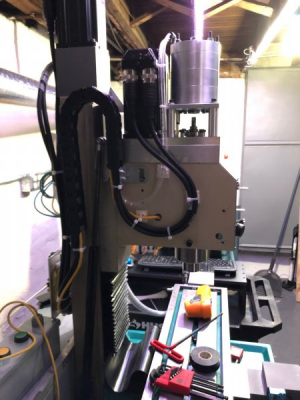
On my previous upgrade to the G0704, I designed a moderately complicated spindle belt drive and pneumatic drawbar assembly. This took advantage of a 1.8kW, 5000 RPM, 4.2 Nm continuous torque, 11.1 Nm peak torque, 90mm frame AC servo I had access to. I chose to use GT3 5mm pitch curvilinear timing belts for synchronous motion (needed for rigid tapping) and smooth running even at high speed. With a later addition of some serial scripting to the spindle drive, I added a real time load monitor for the spindle. I have been absolutely thrilled by this modification and remains one of the most successful designs I've built.
1682704182354.png

For years I've been using this and contemplating the most optimal spindle design for a mill of this size. I'll link to a couple discussions we had here on this site.


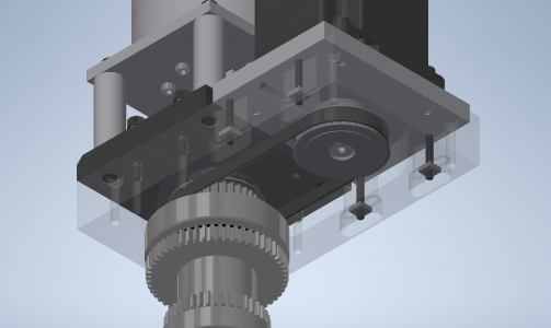
My uses of this machine seem to revolve around 90% aluminum and plastics, and probably 10% steel and cast iron. My most used tool is a 3/8" YG-1 3 flute aluminum cutting endmill. I have found that in 95% of cases I am programming the mill spindle to 5000 RPM at all times. Watching the spindle load meter during my machining, I rarely see it above 20%. This leads me to the conclusion that I did a poor job of selecting the belt ratio for the machine. Fortunately, my belt drive design left it easy to modify and replace the pulleys as needed to achieve various speed configurations.
1682704535200.png

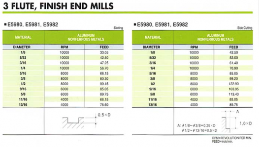
Doing some math, I decided to try to optimize the spindle for use of the YG-1 3/8" endmill and smaller tools. This sacrifices the low end torque of the machine, but again I rarely need that anyways and I should be able to replace the use of large diameter tools with higher performance mid-sized tools. Here is the speeds and feeds chart for the endmill I use the most.
1682704763622.png

We see the recommended side profiling speeds and feeds call for 8000rpm and ~100 ipm @ 25% radial engagement and 100% axial engagement. I've found that my machine runs best at around 15% radial engagement and 200-300% axial engagement with this tool. My normal speeds and feeds are 5000 rpm and 40 ipm.

Using the speeds and feeds calculator, we can see what horsepower and torque are needed for the cut. I've previously measured my total spindle efficiency of 92% and use a unit power for 6061-T6 aluminum and a honed edge tool of 0.4 HP/in^3/min.
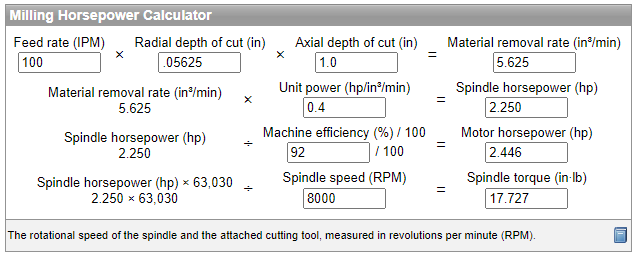
1682706274910.png

2.45 HP equates to exactly 1.8 kW (the continuous rating of my servo), and 17.7 in-lb is equal to 2.0 Nm of torque. With a 1:2 belt drive, this cut would be in the continuous power regime of the motor (meaning I have the full 1.8kW available) and the motor should be able to produce 2.1 Nm torque continuously. Honestly I think the machine rigidity and coolant requirements would limit this cut before the spindle load does.
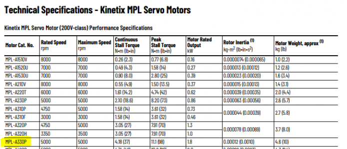
1682706495111.png

This leads me to the conclusion that the 1:2 belt drive configuration is ideal for 3/8" and smaller tooling in aluminum. The spindle should have plenty of torque for milling steel, where I am significantly more limited in machine rigidity than spindle power. I will suffer in the torque needed for larger drills. Some rough calculations show that where I could push a 1/2" drill before, I will now be limited to roughly a 3/8" drill under the same cutting conditions. I rarely use drills over 1/4" and when I do need to, I can adjust the cutting parameters to account for the torque limitations.

In the same line of thought, lets consider rigid tapping (not that I've even actually used it). My 1:1 spindle could offer 4.2 Nm (37 in-lb) continuous torque, and the proposed 2:1 spindle offers 2.1 Nm (18.6 in-lb). The table below shows common tapping torques for sharp ground taps:
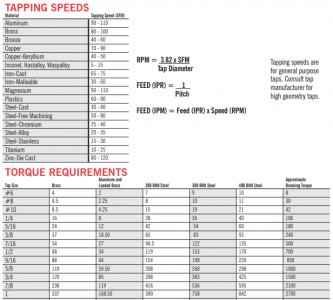
1682709550841.png
1682709567463.png

So, hypothetically I should be able to still drive a 1/4" tap in brass, 3/8" in aluminum, and #10 in mild steel. The spindle will happily offer 300% torque for a short while if needed. The 1:2 spindle maintains the ability to orient and index the spindle via the spindle motor marker, allowing for pack tapping if needed. other ratios such as 2:3 would not permit this.

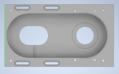
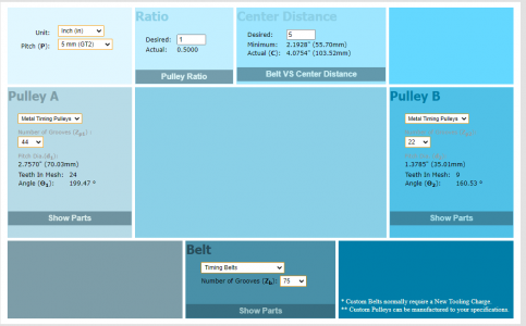
OK, so cool, I'm going with a 1:2 spindle belt ratio. I like to purchase pulleys from SDP-SI and they have a wide variety of offerings for the GT3 5mm size. The main limitation is the small pulley needs to fit over the spindle spline shaft and have keys installed. This creates a minimum size pulley for the driven side of 22T. This means the larger pulley will need to be 44T. I did not plan ahead very well and did not leave sufficient clearance in the spindle housing for the pulley. It will need to be removed and opened up a bit for better clearance. Since this will take the mill out of commission, I needed a friend to give me a hand with the machining.

Before:
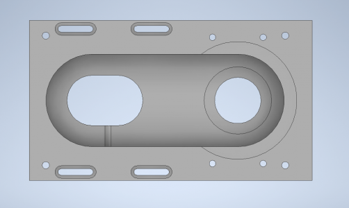
01.PNG

After:
02.PNG

The large driver pulley is not offered with flanges, however a lower flange is required for vertical installation such as this. I will need to design, machine, and install a lower flange so the belt cannot fall off the bottom of the pulley.

Before I go further, I wanted to check that the belt can sufficiently handle the loads and speeds of the application. Gates (the PowerGrip GT3 manufacturer and licenser) has a great design manual HERE.

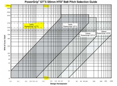
The speed/power chart shows that the GT3 5mm pitch belt is suitable for 10,000 rpm at the faster pulley and up to 10HP. Additional notes in the manual suggest the top speed to be around 14,000 rpm with special design considerations.
1682710247259.png

In the Flange Design section of the manual, the following guidance is offered for vertical installation of belts:

"On vertical shaft drives, one sprocket should be flanged on both sides, and all the other sprockets in the system should be flanged on the bottom side only."

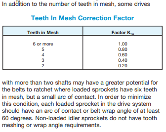
Finally we need to make sure that the minimum teeth in engagement and belt wrap angle are respected. For this the following guidance is offered:
1682710490397.png
Using their online calculator, I was able to select the required pulleys and belts. Notice that both pulleys have >6 teeth in mesh and a wrap angle >60 degrees. The belt length (75T) was selected to give as close to 4.05" center to center distance. This means the new belt drive will fit into the spindle housing with no further modifications needed beyond opening the housing for a bit more clearance.
1682710630789.png
With these changes, I've left myself room to install up to a 50T driver pulley allowing up to 12,000 RPM (with a small tweak on the servo speed maximum on the drive). However, I don't think that any additional speed will be worth the torque tradeoff.

Overall the pulleys should be fairly straightforward to machine, and I'll post updates here.

There are a few concerns with the higher spindle speeds:
  • Thermal heating in the bearings and belts creating higher than desired temperature rise in headstock. The spindle currently stabilizes at ~110*F @ 5000 rpm. This will increase substantially with higher speed.​
  • Spindle balance. The R8 spindle is not balanced and additional speed will increase vibrations. I will need to take care to keep everything concentric to my best ability.​
  • Bearing wear will be increased. The angular contact and deep groove bearings selected have a maximum speed of 14,000 RPM with grease, but the higher speed will increase wear.​
  • TTS tool holders are limited to 10,000 RPM according to Tormach.​
  • I've sent a boring head to 5000 RPM before on accident and it was terrifying. 10,000 RPM could make that situation downright dangerous.​
  • Reduced spindle clamp force. At higher speeds, the centrifugal force on the petals of the R8 collet will tend to make them "open" and decrease the clamping force on the tool shank. I am investigating increasing the drawbar clamp force.​
  • Noise will be significantly increased. The downside of the synchronous timing belt is that it runs much louder than say a poly-V belt. The GT3 curvilinear tooth profile and nylon fabric face on the belt do quite a lot to reduce running noise, but I expect 10,000 RPM will get quite loud. I will maintain the airtight belt drive housing to help with this and may consider adding felt facing to the interior walls of the belt housing for additional sound damping.​
That's all for the moment.

-Mike
 
Last edited:
Making progress on the 10,000 RPM spindle design.

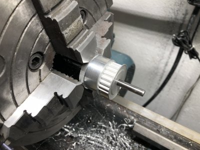
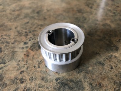
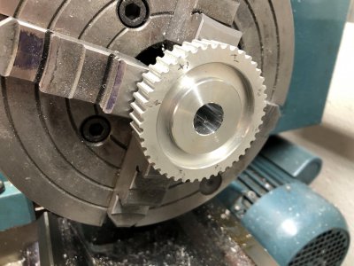
Started with a stock pulley from SDP-SI (22T, GT3, 5mm pitch, 9mm width). I needed to press a collar on the hub in order to increase the diameter. Much care was taken to align the part in a 4-jaw chuck to minimize runout at the pulley teeth and reduce axial runout. I was able to get within 0.0003" TIR in both radial and axial (over 1.5") directions. Interestingly the factory bore on the pulley had nearly 0.0015" runout and was a poor place to measure from.

image001.jpg

This was permanently attached with Loctite 609 retaining compound. This will fit snugly in the upper spindle tube of the G0704 factory spindle assembly.

image003.jpg

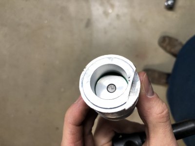
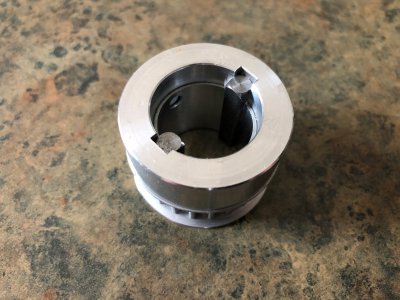
The small pulley was bored to a 0.0003" slip fit over the spindle spline OD. I then used a custom made double broach bushing to add opposing 5mm keyways.

image010.jpg

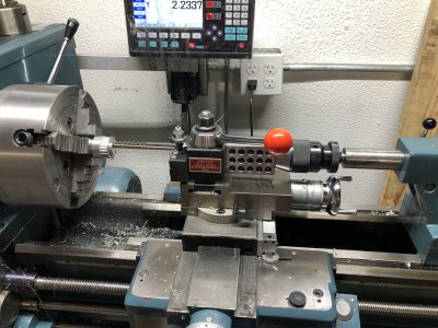
I do not own an arbor press, but I was able to use my lathe to drive the broach through the part. Most of the force is applied by the tailstock screw pushing in line against the toolpost and resting the back of the broach on the toolpost as well. This isn't great and I don't know how much I can recommend it, but it was a successful method to broach the keyways.

image012.jpg

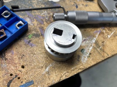
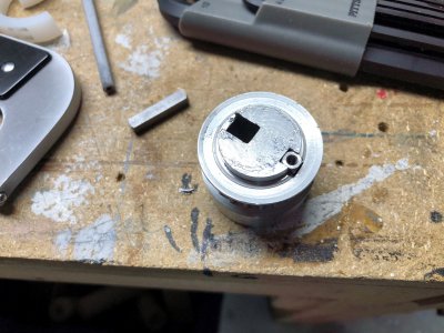
Once one keyway is cut, the double bushing is flipped 180 degrees and a key is installed to lock the orientation. The second keyway is then broached just like the first. I made a pair of 5mm keys with 4-40 tapped holes in the end to facilitate removal from a blind hole.

image014.jpg

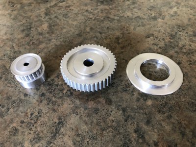
Here is the completed 22 tooth pulley for the driven side of the spindle. The keys will be hand fit by file to the spindle spline for a snug transitional fit.

image015.jpg

image016.jpg

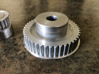
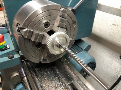
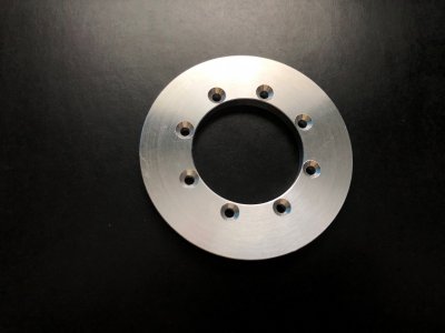
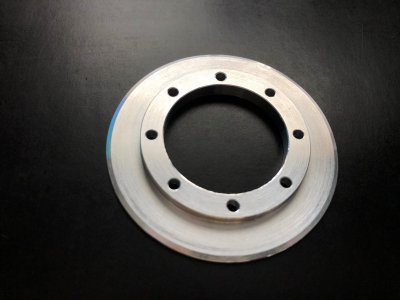
I also machined the flange for the large pulley (far right). This was cut from 3.5" stock with a 20.5 degree bevel to match the factory flanges on the small pulley. The features you see here were machined first, then the part was cut from the stock, flipped over, and faced to thickness using a CA glue chuck method.

image006.jpg

Here is the flange installed on the big pulley. I still need to bore the big pulley to 16mm with a 5mm key, and drill/tap a bolt hole pattern to attach the flange to the pulley.

image008.jpg

I'm hoping to finish the pulleys this weekend so I can deliver the spindle housing to a friend to have some clearance cuts made. Once I get that back, I should be able to install the pulleys and belts on the mill to complete the spindle modification.
 
Bored and broached the motor side driving pulley.

The pulley was indicated within 0.0004" radially and 0.0004" axially at the teeth. I don't think I can get much better than this since the pulley teeth themselves have a couple tenths of deviation from round from the hobbing operation.

The bore was cut to 16mm +0.0004" and the motor shaft is 16mm + 0.0002". This gave a super nice slip fit that required a touch of pressure to assemble. My lathe doesn't cut with much taper after careful leveling otherwise this fit would be hard to achieve. I used a CCGT09T302 aluminum cutting ground insert with a 0.008" nose radius. This let me skim the bore to open it up by about 2 tenths at a time to dial in the fit.

image018.jpg

Similar to the other pulley, this one was broached with a 5mm keyway.

image019.jpg

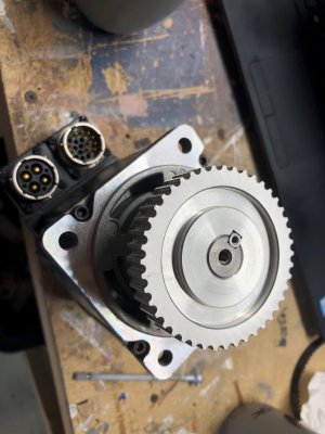
Here it is assembled to a motor with another 5mm key tapped 4-40 on the end. There is zero play and it requires about 10 lbs of force to install on the motor shaft. There are 2 setscrews which will be tipped with brass and installed to prevent the pulley from moving off the motor shaft.

image020.jpg

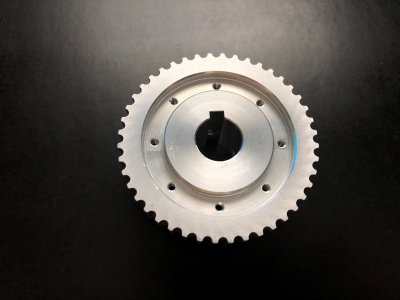
All that is left is to drill an 8 bolt pattern in the trepan web of this pulley and tap them 4-40, then machine the matching pattern in the pulley flange to permit them to be assembled.
 
Spindle pulleys are done:

(8) 4-40 holes are tapped into the trepan web.

image023.jpg

The pulley flange has 8 clearance holes with countersinks drilled to match.

image024.jpg

Here is the bottom side of the flange. The critical feature is the 20.5 degree bevel at the very rim. Everything else is just to mount the flange.

image026.jpg

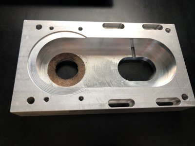
Here is the spindle belt drive housing. I'm dropping it off with a friend tomorrow to have the inner cavity opened up.

image025.jpg

Had a bear of a time removing the old pulley. That one was a light press fit to the motor shaft and did not want to come off without a fight.

Didn't take photos, but I faced and blind drilled the ends of the setscrews that came with the pulleys. Then I turned little brass plugs and pressed them into the ends of the screws with a vise. Finally the brass tips were faced and trued up. The brass tipped screws hold better than plain setscrews and don't mar the motor shaft which could make removal difficult,

Once the housing is done, I should be able to assemble the spindle. I do still need to remove the existing spindle pulley and fit the new keys to the spindle spline.
 
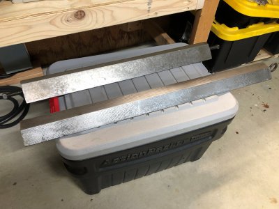
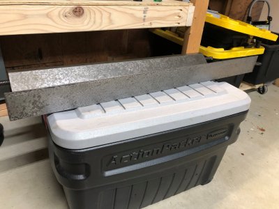
A friend clued me into a pair of hand scraped cast iron dovetail straightedges at a salvage yard for a price so criminally low I won't mention it here. Both are ~42 degrees and have 2 scraped faces. The longer one is 37" and the short one is 30". The longer one is nearly perfect with the exception of one small ding at the very end which needs to be gently stoned down. The 30" one has some significant rusting along the right angle corner, but the scraping on the bottom near the dovetail and the dovetail face itself are in great shape. Hopefully some evaporust will help.

image027.jpg

Contact is fairly even along the entire surface. There are few scratches. The larger one is slightly ribbed in the back to save on weight while the 30" one is solid. Only downside to these is that they are HEAVY! I may need to rig some sort of overhead counter balance to help with printing the ways.

image028.jpg

The 37" is longer than the diagonal of my 18x24" surface plate. I will not be able to fully check its flatness against the plate. This does greatly expand the capacity I can scrape, assuming the previous owner did as good of a job scraping in this tool as it appears they did. I will check local flatness to the best of my abilities.

I'll be using these to scrape in the ways of the mill when I get there. I ordered a spare saddle and Z axis slide from Grizzly. This will allow me to use my mill to add oiling channels since I couldn't mill the existing parts if the mill were disassembled. This will also let me do much of the scraping without having the mill completely taken apart.
 
This next post is somewhat for myself to keep my head straight.

Plan for Quantifying Machine Starting and Ending Accuracy

In order to determine what exactly needs to be corrected, and to quantify how much improvement I have made on the machine, I need a set of parameters to measure. I'd like to say that much of this information was introduced to me for the first time over a decade ago in a CNCZone post titled "Ryan's G0704". This is by far one of the most impressive CNC builds I've ever followed and unfortunately the details of which have been lost to the internet when the 'Zone had a server crash and lost many of the photos from old threads. I've had a bit of luck sifting through the WaybackMachine (Internet Archive) to pull pictures from before 2022.

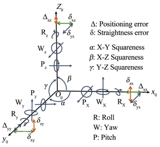
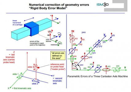
Anyways, Ryan introduced me to a bit of research on machine design and volumetric accuracy. Volumetric accuracy and the corresponding Volumetric error is defined as ability of a machine to produce accurate three-dimensional parts. It is the sum of the deviations from ideal machine movement stemming not only from the accuracy of the screws, but all of the effects of way straightness and orthogonality (3 axis squareness). Research papers will tell you that there are 21 geometric errors in a 3 axis machine (7 for each axis). The figure below depicts the errors on a cartesian triad:

1684502064905.png

Notice that for each axis we have the following errors:
  • Positioning error (X, Y, Z) - contribution of screw lead error, motor positioning error, torsional compliance in the motor screw system, and similar effects
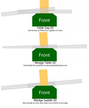
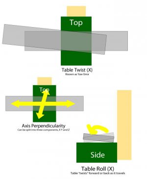
  • Straightness Error (XY, XZ, YX, YZ, ZX, ZY) - movement in axes other than the one being moved. For example, I move X axis 1" to the right, but also get 0.001" movement in Y and 0.003" in Z. Ryan coined the term wedge saddle and wedge table to describe these errors and that makes a good deal of sense to me.
  • Squareness Error (XY, XZ, YZ)- contribution of the angular misalignments between each axis. This might make the most sense to some of us as this is the error you correct when aligning the machine column to the table top.
  • Roll/Pitch/Yaw (X, Y, Z) - these errors occur if the ways are not straight, but rather curved or wavy. Even if all the other errors were zero, moving the X axis (if it had curvy ways in all 3 dimensions) would result in a net movement of X, Y, and Z.
The tricky part is that taking an indicator reading on the table shows you the net contribution of all of these errors. It is very tricky to isolate them when measuring. To the best of my knowledge, this is done in industry with a laser interferometric equipment.

The errors listed above assume a perfect machine without slop or play in the ways, and do not account for the spindle and work holding. For my purposes, these matter as well and I'd like to add a few additional errors I will try to minimize:
  • X slop in Y - TIR on workpiece when X axis is torqued about the Z axis, measured in Y axis direction
  • X slop in Z - TIR on workpiece when X axis is torqued about the Y axis, measured in Z axis direction
  • Y slop in X - TIR on workpiece when Y axis is torqued about the Z axis, measured in X axis direction
  • Y slop in Z - TIR on workpiece when Y axis is torqued about the X axis, measured in Z axis direction
  • Z slop in X - TIR on workpiece when Z axis is torqued about the Y axis, measured in X axis direction
  • Z slop in Y - TIR on workpiece when Z axis is torqued about the X axis, measured in Y axis direction
  • Backlash in X - Leadscrew backlash plus screw support play in X axis
  • Backlash in Y - Leadscrew backlash plus screw support play in Y axis
  • Backlash in Z - Leadscrew backlash plus screw support play in Z axis
  • Spindle tram X - Squareness of the spindle axis to the table in the X direction
  • Spindle tram Y - Squareness of the spindle axis to the table in the Y direction
  • Spindle runout TIR - Runout at the spindle taper
  • Spindle taper angle - Accuracy of the spindle taper angle to the R8 taper standard. Affects TTS tool clamping performance
I will be unable to accurately measure the positioning error of the axis without spending a few hundred to install glass scales, so I will simply go off of the specifications for the ballscrews. Roton claims 0.009" lead error per 12" (no claims about lead "drunkness" - yes this is a real term - which refers to lead variation which is cyclic over 1 screw revolution). The screws I intend to install are C5 grade and are specified for a lead error of 0.001" per 12" and a cyclic error (within any ~0.2") not to exceed 0.0008". These screws would represent almost a 10x improvement over the screws I have. I am also fighting with substantial backlash even after repacking the screws several times. This will be easy to measure. The new screws will come with user adjustable preload using a rotating collar between the double ballnuts. I should be take these down to zero backlash and apply some static preload.

While it may be difficult to directly measure the straightness, squareness, and RPY errors in the machine geometry, I will take some measurements of the total composite error using a granite square and a cylindrical square. These can be used as benchmarks to see how the total machine accuracy improves after scraping. Each individual part will be able to be measured during the scraping process independent of the machine to quantify the accuracy.

At this time, my goal is not to complete a full scrape of the entire machine, but rather to focus on the 20% of the effort to correct the glaring errors and hopefully get 80% of the benefits. I have a feeling this project will extend to a deeper dive in scraping than I plan on, but hey, if it is fun, I'm OK with that.

I will not address the spindle taper until the very end. I am hoping I can cut the taper on the machine itself in its own bearings with a PCD turning tool, but if the machine has significant geometric errors, this could ruin the spindle taper.

My next step is to benchmark the machine accuracy as it stands today.

EDIT: I've managed to pull some of the great graphics that Ryan (CNCZone G0704 project) made from an internet archive search. I'll attach them here so hopefully they might help someone else too.

44488771.jpg
93193101.jpg
81576914.jpg
 
Last edited:
Back
Top