-
Welcome back Guest! Did you know you can mentor other members here at H-M? If not, please check out our Relaunch of Hobby Machinist Mentoring Program!
You are using an out of date browser. It may not display this or other websites correctly.
You should upgrade or use an alternative browser.
You should upgrade or use an alternative browser.
Mike's CNC G0704 - Block 4 Upgrades
- Thread starter macardoso
- Start date
- Joined
- Mar 26, 2018
- Messages
- 2,724
Thanks Mike for the detailed write up; that will make a wonderful resource for how to make these assessments.
Sent from my iPhone using Tapatalk Pro
Thanks guys! Making slow progress forward, but finding little time to write up my progress. Hopefully more to come soon!Wow, this is a great thread!
- Joined
- Mar 26, 2018
- Messages
- 2,724
Mill Head Casting:
Made significant progress in scraping the mill head casting interface surface. It is not done yet, but getting close. Waiting on some test bars to scrape for final alignment.
I also want to apologize for all the scraping photos you'll see in this thread. It is very difficult to get a good photo of the bluing for some reason and the photos are either washed out or very dark and hard to see. I will keep messing with the lighting to try to get it better.
As I've shown before, this is the state of the casting after the breakup pass. The left quarter is shallow by a whopping 3 thou and there is a 1.5 thou hollow in the bottom right. My scraping goal is 10-15 ppi and parallel to the spindle axis within 0.0002" (unilateral, low in Z+ direction only).
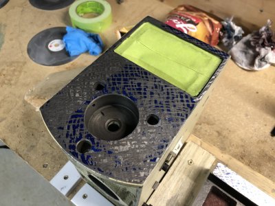
After 5 passes, I've filled in the right hollow, but the left is still very low. At this point I'm still heavily roughing and simply avoiding the sharpie marked areas.
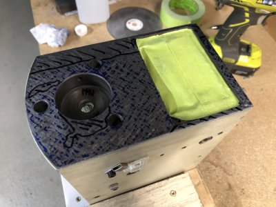
Here is after 12 passes. You can see I am walking the contact patch steadily left. Each pass is taken at 90 degrees to the last.
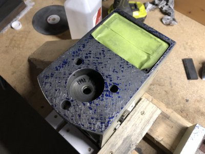
And at 14 passes, nearly full contact is made along the left, although the surface is not very flat. I also made a huge mistake thinking I could use a diamond lapping plate to help with roughing in contact. About 20 seconds of lapping by hand hollowed out the middle (especially by the rectangular window so much that it took hours to correct the damage).
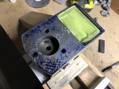
19 passes. Look at the hollow near the rectangular window. Had to remove over a thou of additional material to bring this back into contact.
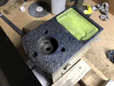
And here is the casting at 24 passes, with a little contrast. Showing good contact everywhere (maybe a little hollow in the lower right). This is as far as I have gone so far. I don't want to try to do any finishing work until I correct alignment.
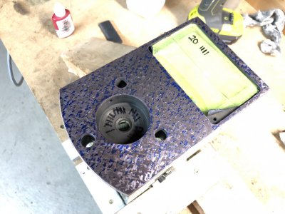
I ordered some linear shafting from McMaster Carr to be used as a test bar. I couldn't stomach the $500 for a true R8 test bar from Glacern. Hopefully this stuff is good enough (~$20 per bar). I ordered some 1/2", 5/8", and 3/4" for checking alignment all over the machine. I'll still be including error from the collet, but I should be able to average that out by measuring the test bar at 180 degree rotations.
Made significant progress in scraping the mill head casting interface surface. It is not done yet, but getting close. Waiting on some test bars to scrape for final alignment.
I also want to apologize for all the scraping photos you'll see in this thread. It is very difficult to get a good photo of the bluing for some reason and the photos are either washed out or very dark and hard to see. I will keep messing with the lighting to try to get it better.
As I've shown before, this is the state of the casting after the breakup pass. The left quarter is shallow by a whopping 3 thou and there is a 1.5 thou hollow in the bottom right. My scraping goal is 10-15 ppi and parallel to the spindle axis within 0.0002" (unilateral, low in Z+ direction only).

After 5 passes, I've filled in the right hollow, but the left is still very low. At this point I'm still heavily roughing and simply avoiding the sharpie marked areas.

Here is after 12 passes. You can see I am walking the contact patch steadily left. Each pass is taken at 90 degrees to the last.

And at 14 passes, nearly full contact is made along the left, although the surface is not very flat. I also made a huge mistake thinking I could use a diamond lapping plate to help with roughing in contact. About 20 seconds of lapping by hand hollowed out the middle (especially by the rectangular window so much that it took hours to correct the damage).

19 passes. Look at the hollow near the rectangular window. Had to remove over a thou of additional material to bring this back into contact.

And here is the casting at 24 passes, with a little contrast. Showing good contact everywhere (maybe a little hollow in the lower right). This is as far as I have gone so far. I don't want to try to do any finishing work until I correct alignment.

I ordered some linear shafting from McMaster Carr to be used as a test bar. I couldn't stomach the $500 for a true R8 test bar from Glacern. Hopefully this stuff is good enough (~$20 per bar). I ordered some 1/2", 5/8", and 3/4" for checking alignment all over the machine. I'll still be including error from the collet, but I should be able to average that out by measuring the test bar at 180 degree rotations.
- Joined
- Mar 26, 2018
- Messages
- 2,724
I spent a long time pondering the order of operations for scraping. There are a lot of "chicken before the egg" situations and I needed a concrete plan. I also needed to understand the tools I need to complete the work. I'll detail the order of operations in the next post, but here is the list of tools I expect to need:
- Surface plate (18x24) - Used for spotting most surfaces. A 24x36" would be much better but I cannot easily carry it down the basement.
- Hand scraper - I bought the 20mm Sandvik scraper. I like the inserts a lot, but the handle is a bit short and stiff.
- Marking Compound - Dykem HiSpot blue or Charbanol Prussian Blue oil paint
- Scrapers Block - I use a 1.18” diameter optical flat. Cheap and guaranteed flat and parallel
- Stones - for deburring. I have flat ground stones as well as some Arkansas stones.
- 0.0001” dial test indicator on toolmakers stand
- Height gauge - for rough measurements of surfaces
- Dovetail or angle straightedge - I have 2 options, a 37” and a 30” scraped angle straightedge. Necessary for marking the dovetail ways for scraping. Both need some care.
- Cylindrical Square - for checking column squareness
- Granite Tri-Square - for checking XY squareness. Could be used for column, but cylindrical square is easier.
- (2) 0.5” x 12” test bars - for checking dovetail parallelism.
- 0.625” x 18” test bar - for checking saddle squareness
- 0.75” x 12” test bar - for checking spindle parallelism
- Gage blocks or adjustable parallels - for precise measurement of dovetail dimension and parallelism between test bars
- Micrometer set - for precise measurement of dovetail dimension and parallelism over test bars
- Sine bar - for measurement of tapered gibs.
Last edited:
- Joined
- Apr 21, 2015
- Messages
- 582
Great stuff, Mike! Glad I found your thread.
I didn't realize until your last post that you're scraping this whole mill without a power scraper. Whoof - you must be a patient man! That was VERY smart to purchase extra castings so you have a working mill during the project.
A few comments/questions (as requested):
I didn't realize until your last post that you're scraping this whole mill without a power scraper. Whoof - you must be a patient man! That was VERY smart to purchase extra castings so you have a working mill during the project.
A few comments/questions (as requested):
- You measured slop, but I didn't see any mention of checking and tightening the gibs. You might be well served checking the gibs for straightness. 0.009" of movement from racking the table seems a little excessive, but you'll need at least a little play of course, or the table will be too hard to move.
- I have to keep reminding myself that this is a CNC project with ball screws, neither of which have I any experience in, so take my comments with a VERY large grain of salt.
- On my (G0762) manual square-column benchtop mill, the most important travel is X & Y of the table and quill movement in Z. I mostly just get the head close, lock it in place, and use the quill to move the tool in Z, so the Z ways are actually less critical to me and see much less wear. I still want Z at least close, of course, but X, Y, and quill get CONSTANT use.
- I don't understand your head tram measurement relative to X. Can't you tilt your head to get it close to zero? The photo from the Grizzly website makes it look like the head can tilt like my mill (and most vertical mills).
- The nod on my G0762 can only be addressed by scraping/shimming (or moglice/whatever). There are two surfaces that must be adjusted: where the head attaches to the Z-saddle, and where the column attaches to the base. Ideally, both should be exactly 90°.
- If it was reasonably close to begin with, it would be best to attempt to "scrape straight down" on that head casting surface you're currently working on, otherwise you may have to do quite a bit more scraping to make it orthogonal when you get your test rod. It can sometimes be quite a bit more efficient to "tip in" while scraping if you're just trying to make something flat, but in this case it's probably best to scrape "straight down".
- The linear shafting should be fine for a test rod. Just roll it on your plate with a bright flashlight behind to ensure it wasn't bent in transit, and mic it at various points to ensure its the same diameter everywhere (within a couple tenths). I'd be very surprised if it isn't much more accurately ground than the specs.
- No matter how much care you take and how good your collets are, you'll likely get some runout at the end of the test bar. This is NOT a problem. Just indicate at two points and ensure you rotate the spindle until the reading is exactly halfway between the min and max deviation at that rotation. When that's true, the line between the two points under the indicator tip is exactly parallel to the axis of rotation (both points will be on the same side unless the shafting is bent). Just remember to repeat the rotation when you measure against the orthogonal axis (say once along the right side of the shaft to check tilt, and once on the front side to measure nod, rotating to the halfway reading for each).
- One suggestion for your equipment list: I find gauge pins far more generally useful than gauge blocks (and much cheaper). Gauge blocks are useful for averaging out a scraped surface, though (letting you measure how deep a hole is, or whatever, with an indicator). I have a complete set of pins up to 0.500" (minus) and I couldn't live without them. For some reason, we all forget that you can use two pins in a hole, so I can measure holes accurately up to 0.999" with my two sets (more accurately than I can with telescoping gauges or whatever). Dowel pins and ejector pins in various sizes also come in handy for all sorts of indicating/locating/positioning tasks.
- I don't know how much I'd trust those long triangular straightedges you obtained -- even camelbacks can move a surprising amount. Definitely store them by hanging from the ends, though -- laying them flat is just asking for trouble. I'm curious how well they mark up on your plate (and against each other).
- Why do you need 12" test bars for checking dovetails? Can't you just use short hardened and ground pins of known diameter?
- Joined
- Mar 26, 2018
- Messages
- 2,724
You measured slop, but I didn't see any mention of checking and tightening the gibs. You might be well served checking the gibs for straightness. 0.009" of movement from racking the table seems a little excessive, but you'll need at least a little play of course, or the table will be too hard to move.
I chose to evaluate the machine in the exact state that it has been used in for the past 8 years or so. I could have improved the measurements by tightening the gibs, but that would cause binding in some parts of travel and would require shims behind the gibs since they are currently maxed out. I felt that evaluating the machine without tuning it up would give the best comparison between the old and upgraded states of the machine in actual use.
I have to keep reminding myself that this is a CNC project with ball screws, neither of which have I any experience in, so take my comments with a VERY large grain of salt.
I don't think scraping methods and machine alignment will change much between CNC and manual machines. But I certainly can be wrong.
On my (G0762) manual square-column benchtop mill, the most important travel is X & Y of the table and quill movement in Z. I mostly just get the head close, lock it in place, and use the quill to move the tool in Z, so the Z ways are actually less critical to me and see much less wear. I still want Z at least close, of course, but X, Y, and quill get CONSTANT use.
I have disabled the use of my quill in favor of a high speed belt drive. The spline fit was too sloppy to permit high speed drive through the spline interface, and implementing a belt drive on this machine while maintaining the quill function was significantly more complicated. For this reason my column experiences a ton of Z axis travel and will need to be scraped for proper alignment and way function.
don't understand your head tram measurement relative to X. Can't you tilt your head to get it close to zero? The photo from the Grizzly website makes it look like the head can tilt like my mill (and most vertical mills).
Yeah, the head tilts. Apparently it was been way out of tram for a while. Shame on me. I reported the current state of the machine. This should be able to be adjusted to zero in the X direction without scraping.
The nod on my G0762 can only be addressed by scraping/shimming (or moglice/whatever). There are two surfaces that must be adjusted: where the head attaches to the Z-saddle, and where the column attaches to the base. Ideally, both should be exactly 90°.
I have finished the scraping on the mill head casting and partially on the Z axis slide. When I finish the column, I will ensure the alignment of the 3 components yields zero nod.
If it was reasonably close to begin with, it would be best to attempt to "scrape straight down" on that head casting surface you're currently working on, otherwise you may have to do quite a bit more scraping to make it orthogonal when you get your test rod. It can sometimes be quite a bit more efficient to "tip in" while scraping if you're just trying to make something flat, but in this case it's probably best to scrape "straight down".
Head casting is done - will write a post with details when I have a chance.
The linear shafting should be fine for a test rod. Just roll it on your plate with a bright flashlight behind to ensure it wasn't bent in transit, and mic it at various points to ensure its the same diameter everywhere (within a couple tenths). I'd be very surprised if it isn't much more accurately ground than the specs.
Ended up being bowed about 0.0008"/12". Not great, not terrible. Developed a test method that negates the contribution of bent test bar error during measurement.
No matter how much care you take and how good your collets are, you'll likely get some runout at the end of the test bar. This is NOT a problem. Just indicate at two points and ensure you rotate the spindle until the reading is exactly halfway between the min and max deviation at that rotation. When that's true, the line between the two points under the indicator tip is exactly parallel to the axis of rotation (both points will be on the same side unless the shafting is bent). Just remember to repeat the rotation when you measure against the orthogonal axis (say once along the right side of the shaft to check tilt, and once on the front side to measure nod, rotating to the halfway reading for each).
I'll detail in my next post, but I found this doesn't work well for compound errors (spindle angular runout + bent test bar). I developed a measurement method that yields reliable readings independent of these factors as long as the test bar is round to a fairly good degree.
One suggestion for your equipment list: I find gauge pins far more generally useful than gauge blocks (and much cheaper). Gauge blocks are useful for averaging out a scraped surface, though (letting you measure how deep a hole is, or whatever, with an indicator). I have a complete set of pins up to 0.500" (minus) and I couldn't live without them. For some reason, we all forget that you can use two pins in a hole, so I can measure holes accurately up to 0.999" with my two sets (more accurately than I can with telescoping gauges or whatever). Dowel pins and ejector pins in various sizes also come in handy for all sorts of indicating/locating/positioning tasks.
I don't own gage pins or blocks currently. My only draw to gage blocks over pins is that I have a few parts of this restoration that will require setting up a sine bar, and having gage blocks for that would be useful I think. A Grade B set from Shars should be accurate enough for my needs and only costs about $120.
I don't know how much I'd trust those long triangular straightedges you obtained -- even camelbacks can move a surprising amount. Definitely store them by hanging from the ends, though -- laying them flat is just asking for trouble. I'm curious how well they mark up on your plate (and against each other).
In the process of checking these. Both need to be touched up with some scraping passes. Will store them vertically, thanks for the tip! I wish I had a camelback dovetail straightedge, but I paid $20 for the pair of these and I'm just happy to have them!
Why do you need 12" test bars for checking dovetails? Can't you just use short hardened and ground pins of known diameter?
I don't own any pins except for endmill shanks. The linear shafting was quite inexpensive and I figured it would be good for averaging the scraping of the dovetails over a useful distance, similar to how the mating member will fit. Bluing markup from the straightedge should show flatness, and the test bars will allow me to mic the dovetails for parallelism.
- Joined
- Mar 26, 2018
- Messages
- 2,724
Order of operations (work in progress)
Mill base
Mill saddle
Mill Table
Mill column
Z axis slide
Mill Head
X, Y, & Z Gibs
Tools needed:
Mill base
- Scrape bottom of casting flat and roughly parallel to flat ways
- Scrape flat ways to rough flat
- Finish scrape bottom casting to 5ppi
- Finish scrape flat ways to 20ppi, coplanar to each other and parallel to casting bottom within 0.0002”
- Rough Scrape dovetail ways
- Check dovetail ways over test bars for parallelism
- Check dovetail ways for angular match to saddle. Mostly correct in saddle but ok to adjust base as well.
- Finish scrape dovetail to 20ppi, parallel to each other within 0.0002” over full length.
- Rough scrape column mounting, correct perpendicularity to flat ways
- Finish scrape column mounting to 5ppi and perpendicular to flat ways within 0.0002”
- (2) 0.5” test bars
- Micrometer
- Dovetail straightedge.
- Height gauge
- 0.0001” indicator on stand
- Optical flat
- Tool room stones
- Granite square or cylindrical square.
Mill saddle
- Rough Scrape lower flat ways to 5ppi
- Rough scrape upper flat ways to 5ppi parallel to upper flat ways
- Finish scrape lower flat ways to 20ppi
- Finish scrape upper flat ways to 20ppi, parallel to lower ways within 0.0002”
- Rough scrape bottom dovetail way check surface
- Finish scrape bottom dovetail way check surface to 5ppi and parallel to flat ways within 0.0002”
- Rough scrape top dovetail way check surface
- Finish scrape top dovetail way check surface to 5ppi and parallel to flat ways within 0.0002”
- Rough scrape bottom dovetail ways. Match angle to base. Use gib to set fixed dovetail taper angle.
- Rough scrape top dovetail ways. Match angle to table. Use gib to set fixed dovetail taper angle.
- Finish scrape bottom dovetail ways to 20ppi (sliding) and 5ppi (fixed). Match dovetail angle to base until full contact. Use gib to set fixed dovetail taper angle within 0.0002” of parallel with gib installed using test bars.
- Finish scrape top dovetail ways to 20ppi (sliding) and 5ppi (fixed). Match dovetail angle to table until full contact. Use gib to set fixed dovetail taper angle within 0.0002” of parallel with gib installed using test bars. Scrape top sliding way perpendicular to bottom sliding way within 0.0002” using test bars and granite square.
- Relieve center 50% of all way surfaces with 2 crossed passes to assist wear pattern.
- Mill and drill oiling grooves on all surfaces.
- Deburr oiling grooves with tool room stone
- Mill Base, finish scraped.
- Mill Table, finish scraped.
- X Gib, semi finish scraped
- Y Gib, semi finish scraped
- Assembled milling machine
- Dovetail straightedge
- (2) 0.5” test bars
- (1) 0.625” test bar, 18” long.
- Granite square.
- Gage block set or adjustable parallels.
- Height gauge
- 0.0001” indicator on stand
- Optical flat
- Tool room stones
Mill Table
- Rough scrape top, step scrape if needed to rough in flat way parallelism
- Finish scrape top to 10 ppi
- Rough scrape flat ways for coplanarity and parallelism to top.
- Finish scrape flat ways to 20ppi, coplanar to each other and parallel to top within 0.0002”
- Rough scrape dovetail ways
- Check dovetail ways over test bars for parallelism
- Check dovetail ways for angular match to saddle. Mostly correct in saddle but ok to adjust table as well.
- Finish scrape dovetails to 20ppi, parallel to each other within 0.0002” over full length.
- (2) 0.5” test bars
- Micrometer
- Dovetail straightedge.
- Height gauge
- 0.0001” indicator on stand
- Optical flat
- Tool room stones
Mill column
- Install column bracing and concrete. Use indicator to determine column spine flatness and steel MC channel flatness. Install custom spacers where necessary to minimize warping of spine. Install lots of knurled knobs on sides which will attach to concrete.
- Rough scrape flat ways coplanar
- Rough scrape front face or 3 point pads on column rear as check surface parallel to flat ways.
- Rough scrape dovetail ways parallel. Match angle to z axis slide. Mostly scrape slide, but ok to correct ways too.
- Rough scrape column mount parallel to flat ways.
- Finish scrape front face or 3 point pads on column rear as check surface to 5 ppi and parallel to flat ways.
- Finish scrape flat ways to 20 ppi, parallel to check surface.
- Finish scrape dovetail ways to 20 ppi and parallel measured over test bars within 0.0002”
- Finish scrape column mounting pad to 5ppi and parallel to flat ways within 0.0001”
- column bracing installed and cured.
- Micrometer
- Dovetail straightedge.
- Height gauge
- 0.0001” indicator on stand
- Optical flat
- Tool room stones
Z axis slide
- Rough scrape flat ways
- Finish scrape flat ways to 20ppi and coplanar
- Using finished head casting, Rough scrape front face parallel to flat ways
- Using finished head casting, finish scrape front face to 10-15ppi and parallel within 0.0002” (low side only towards Z+ permissible). Side to side parallelism has no requirement, only top to bottom +/- Z)
- Rough scrape dovetail way check surface parallel to front face
- Finish scrape dovetail way check surface to 5ppi and parallel to front face within 0.0002”
- Rough scrape dovetail ways. Match angle to column. Use gib to set fixed dovetail taper angle by measuring between test bars.
- Finish scrape dovetail ways to 20ppi (sliding) and 5ppi (fixed). Match dovetail angle to column until full contact. Use gib to set fixed dovetail taper angle within 0.0002” of parallel with gib installed using test bars.
- Relieve center 50% of ways with 2 crossed passes to assist wear pattern.
- Mill and drill oiling grooves on all surfaces.
- Deburr oiling grooves with tool room stone
- Column, finish scraped
- Mill head, finish scraped
- Z gib, semi finish scraped
- Assembled milling machine
- Dovetail straightedge
- (2) 0.5” test bars
- Gage blocks or adjustable parallels
- Height gauge
- 0.0001” indicator on stand.
- Optical flat
- Tool room stones
Mill Head
- Rough scrape mill head interface
- Finish scrape mill head interface to 10-15ppi. Ensure parallelism to spindle axis within 0.0002” (low side only towards Z+ permissible). Use R8 collet and 0.75” test bar rotated to median error as reference.
- 0.75” test bar
- 0.0001” indicator on stand
- R8 precision collet
- Optical flat
X, Y, & Z Gibs
- Inspect gibs with indicator and shims, straighten by hand to minimize error before scraping.
- Using a 4” vise with jaws inverted, rough scrape gibs. Use rough measurements of mating way to match angle. Check using sine bar set to complementary angle. Ensure no transverse angle exists.
- File gib edges to permit proper clearance when assembled.
- Semi finish scrape gibs to 10 ppi (sliding) and 5 ppi (static). Ensure transverse taper is <0.0002”.
- Using sine bar, Mill and drill oiling grooves on sliding surface.
- Deburr oiling grooves with tool room stone
- Finish scrape gibs to 20ppi (sliding) and 5ppi (static) using contact bluing by assembling gib into ways (ways carry blue).
- Trim gib to length and file screw reliefs
- Deburr gib ends with tool room stone
- Relieve center 50% of gib sliding surface to assist wear pattern.
Tools needed:
- Assembled milling machine
- Sine bar
- Gage blocks
- 4” vise
- Joined
- Mar 26, 2018
- Messages
- 2,724
Mill Head Casting - Complete
Been a while since I had a chance to post a proper update on my progress. Good news is that the mill head casting scraping is done - here is what it took to get there.
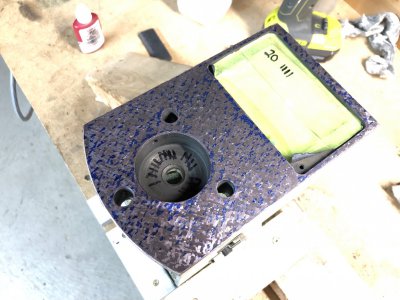
Recap: I have taken 24 passes to get the casting from rough machined to flat at 20+ PPI. The casting had one side rolled off more than 0.004" and a hole over 0.003" deep. I could have reduced the number of passes by not accidentally stoning the casting out of flat with a diamond lapping disc. Here is the coverage at 24 passes.
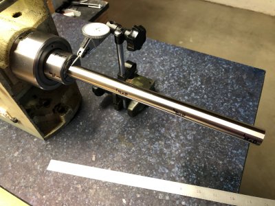
At this point I received the linear motion shaft from McMaster Carr (Thompson brand 3/4" diameter, 12" long), which would be my test bar for the spindle. As a reminder, my goal was to scrape the casting such that the rear plane is parallel to the spindle centerline (as assembled) within 0.0002"/12" permissible to be low in the Z+ direction only. This way, sagging under gravity would tend to decrease error.
My second mistake (after the abrasive lap incident) was to wait until this point to measure the geometric error in the surface. I ended up measuring that the plane was tilted by -0.0034"/12" to the spindle centerline and significant roughing would be required to bring the angle to true. This means any time spent developing flatness beyond minimum bearing (say 5 PPI) was wasted as the surface would be destroyed in the subsequent roughing.
My measuring process differs somewhat from the Rollie Dad's Method (RDM) or the median error method in Machine Tool Reconditioning (MTR). It is slower, but I found to be very accurate and unaffected by runout or test bar straightness. Here are the steps:
One thing I had to learn was how critical it is to fully torque the drawbar during measurements. At first I was snugging the drawbar for measurements and would get variations in measurements by as much as a thou and a half and the measurements wouldn't repeat. Once I started torqueing the drawbar to spec, the measurement variation closed up to within a tenth or two which is about the most I trust my measuring abilities at this scale.
OK, so now we can accurately measure the true spindle centerline against the mounting surface, so I needed to correct the angular error. This is where I started step scraping. This is where you modify a surface's angle by taking more scraping passes on one side than another. I started by taking 2 cycles of: 100% coverage, 75% coverage (favoring high side), 50% coverage, and finally 25% coverage. This ended up being 8 passes and then I took 2 passes to re-flatten the surface to stabilize measurements. The first time I did this, the surface moved by +0.0014"/12" leaving -0.0020"/12" of angular error. I figured that if I was consistent in my scraping, I needed about 3 more step scraping cycles of 4 passes each.
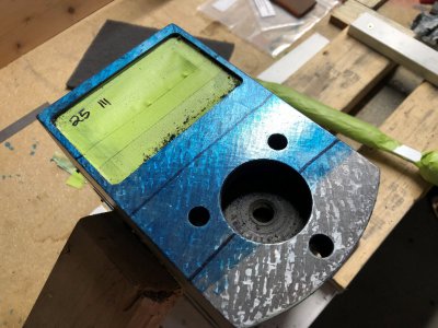
Layout with Canode blue as contrast and lines for blind step scraping. I do not like the canode for marking the part, but find it good for contrast.
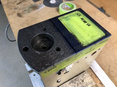
Example of a 50% coverage step scraping pass (blue applied for contrast to see where I've scraped).
Unfortunately I ran into some issues in my plan and the next time I checked the angle, I found the angle changed much less than I expected, only +0.0006"/12" leaving -0.0012"/12" left to correct. I now have some theories about why this is the case, but I didn't understand it at the time. I took a few more step scraping passes to try to move the surface closer to zero and this time it overshot to +0.0006"/12". I tried to stabilize the surface by scraping for flatness and even slightly step scraping in the opposite direction however the surface continued to move the wrong direction, peaking at +0.0012"/12".
I have a few theories why this happened:
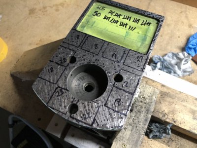
A few things I learned:
1) Measure the entire surface geometry before starting. I first scraped flat, then later corrected the surface angle. Had I know about the angular error, I could have worked to correct both issues at the same time and saved many cycles.
2) I scrape too shallow when roughing, but especially around holes, the perimeter of the part, and delicate thin sections. I have to consciously force myself to scrape harder or take an extra pass in these areas, otherwise I create a valley in the larger solid areas.
3) I drag the scraper on my return stroke. I think it might be better to take individual scrapes without dragging backwards. I’ve seen both ways on videos online. It’s much easier and faster to drag backwards and the only downside seems to be the visual effect and maybe faster tool wear.
In Summary:
The head casting is complete per my order of operations plan posted above. Surface falls within the angular error tolerance of -0"/12" +0.0002"/12" and meets the 10-15PPI all over. This is probably higher than needed for a static bolted connection.
Been a while since I had a chance to post a proper update on my progress. Good news is that the mill head casting scraping is done - here is what it took to get there.
Recap: I have taken 24 passes to get the casting from rough machined to flat at 20+ PPI. The casting had one side rolled off more than 0.004" and a hole over 0.003" deep. I could have reduced the number of passes by not accidentally stoning the casting out of flat with a diamond lapping disc. Here is the coverage at 24 passes.

At this point I received the linear motion shaft from McMaster Carr (Thompson brand 3/4" diameter, 12" long), which would be my test bar for the spindle. As a reminder, my goal was to scrape the casting such that the rear plane is parallel to the spindle centerline (as assembled) within 0.0002"/12" permissible to be low in the Z+ direction only. This way, sagging under gravity would tend to decrease error.
My second mistake (after the abrasive lap incident) was to wait until this point to measure the geometric error in the surface. I ended up measuring that the plane was tilted by -0.0034"/12" to the spindle centerline and significant roughing would be required to bring the angle to true. This means any time spent developing flatness beyond minimum bearing (say 5 PPI) was wasted as the surface would be destroyed in the subsequent roughing.
My measuring process differs somewhat from the Rollie Dad's Method (RDM) or the median error method in Machine Tool Reconditioning (MTR). It is slower, but I found to be very accurate and unaffected by runout or test bar straightness. Here are the steps:
- Mark 8 indexes on the spindle labeled A-H equally spaced every 45*. The more accurately these can be lined up, the better the results.
- Mark repeatable positions along the length of the bar, in my case at 3", 6", and 9" from the spindle nose
- Index spindle to "A" and zero tenths indicator at the spindle nose.
- Record measurements at each measuring position along the bar
- Return to spindle nose and verify indicator repeats to 0
- Index spindle 180 degrees forward (in this example, index "E") and zero indicator at spindle nose
- Record measurements at each measuring position along the bar
- Return to spindle nose and verify indicator repeats to 0
- At each position compute (A_reading - E_reading)/2 to find the rise/fall above zero position
- Compute angular deviation by taking the result of (9) and dividing by the distance along the bar and then normalizing to rise/fall over 12"
- Index forward by 45 degrees (in this example, position "B") and repeat the process for all position pairs spaced apart by 45 degrees
- Average normalized angular deviations from all trials at each position on the bar and verify the measurement deviations are small (1-2 tenths)
One thing I had to learn was how critical it is to fully torque the drawbar during measurements. At first I was snugging the drawbar for measurements and would get variations in measurements by as much as a thou and a half and the measurements wouldn't repeat. Once I started torqueing the drawbar to spec, the measurement variation closed up to within a tenth or two which is about the most I trust my measuring abilities at this scale.

OK, so now we can accurately measure the true spindle centerline against the mounting surface, so I needed to correct the angular error. This is where I started step scraping. This is where you modify a surface's angle by taking more scraping passes on one side than another. I started by taking 2 cycles of: 100% coverage, 75% coverage (favoring high side), 50% coverage, and finally 25% coverage. This ended up being 8 passes and then I took 2 passes to re-flatten the surface to stabilize measurements. The first time I did this, the surface moved by +0.0014"/12" leaving -0.0020"/12" of angular error. I figured that if I was consistent in my scraping, I needed about 3 more step scraping cycles of 4 passes each.
Layout with Canode blue as contrast and lines for blind step scraping. I do not like the canode for marking the part, but find it good for contrast.

Example of a 50% coverage step scraping pass (blue applied for contrast to see where I've scraped).

Unfortunately I ran into some issues in my plan and the next time I checked the angle, I found the angle changed much less than I expected, only +0.0006"/12" leaving -0.0012"/12" left to correct. I now have some theories about why this is the case, but I didn't understand it at the time. I took a few more step scraping passes to try to move the surface closer to zero and this time it overshot to +0.0006"/12". I tried to stabilize the surface by scraping for flatness and even slightly step scraping in the opposite direction however the surface continued to move the wrong direction, peaking at +0.0012"/12".
I have a few theories why this happened:
- My measurements were incorrect due to the drawbar not being fully tightened. This should have averaged out using my method, but I know that that it does not if the bar shifts during measurement
- A term I'll coin as surface "inertia". If you start with a fine surface (as it was after 24 passes) and rough step scrape only part of the surface, you end up with a varied surface roughness along the part. Once you start to apply surface finishing techniques to the entirety of this surface, the areas of higher roughness will lower more than the areas where it is already fairly flat. As such, the finish cuts moved the true plane of the rough side more than that of the finished side as the valleys on the rough side were much deeper and dropped the surface more substantially for each high point removed. This explains why the surface continued to change in angle when I started to apply finish scraping techniques all over the surface.

A few things I learned:
1) Measure the entire surface geometry before starting. I first scraped flat, then later corrected the surface angle. Had I know about the angular error, I could have worked to correct both issues at the same time and saved many cycles.
2) I scrape too shallow when roughing, but especially around holes, the perimeter of the part, and delicate thin sections. I have to consciously force myself to scrape harder or take an extra pass in these areas, otherwise I create a valley in the larger solid areas.
3) I drag the scraper on my return stroke. I think it might be better to take individual scrapes without dragging backwards. I’ve seen both ways on videos online. It’s much easier and faster to drag backwards and the only downside seems to be the visual effect and maybe faster tool wear.
In Summary:
The head casting is complete per my order of operations plan posted above. Surface falls within the angular error tolerance of -0"/12" +0.0002"/12" and meets the 10-15PPI all over. This is probably higher than needed for a static bolted connection.
Last edited:
- Joined
- Mar 26, 2018
- Messages
- 2,724
DISCLAIMER:
I am not an experienced scraper and have only done a few scraping projects for flatness and a vise body for parallelism. I have not taken Richard King's class nor do I intend to show proper methodology. This is a huge learning project for me and I expect I'll make many errors along the way. If the previous post didn't make it clear, I am also not scraping in the most efficient way.
The methods and tools I use are based on what I know about and what I have available to me. I don't have any precision grinding equipment, another milling machine, nor a power scraper. I have a fair collection of metrology tools to help measure the machine geometry.

