Monarch 1944 12" CK

I googled clutch bearings and Mcgill and see your problem. Dave
 
Quick tip. When you get your bearing, don’t over pack it grease. Just lightly. If you do, the grease will cause the bearing to drag and the spindle will still spin. Ask me how I know……. I the read it in the manual. Pays to read first. I had to pull it apart and clean out all the grease and start over. Works as should now.


Sent from my iPhone using Tapatalk
Yeah, I've had my clutch apart for that reason. The grease eventually works its way to the clutch material. Lesson learned the hard way.
 
Going down the rabbit hole ....

The original bearing was a double row needle bearing. I haven't been able to find anything of similar size. McGill makes cageroll bearings that can match the OD or the ID, but they're not cheap. I'm going to replace the old bearing with two 6909 deep groove roller bearings. Those bearings are 45mm x 68mm x 12mm, vs the 1.625 x 2.625 x 2.375 (ID, OD, width) of the original bearing. The metric variation converts to
1.7716" x 2.6771 x .4724" .

So I'll need to bore out the pulley/sheeve by .052" on either side, and make a sleeve for the interior. And make a retaining bushing that properly registers on the inner race of the bearing, to be held in place by a circular retaining ring.

I started putting the 612 cross slide back together today. It's going together as a hack so I can turn the parts for the CK.
 
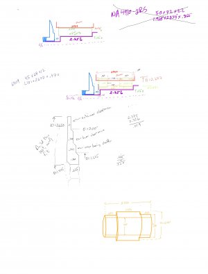
Here’s my doodlings of the clutch bearing mod. These are all round parts, I’ve jst drawn the top half of a cross section. Be nice to (re)learn CAD for this as it is just complicated enough to warrant scaled and dimensionally checked drawings.

Poor quality drawings but it has been 40 years since I took drafting. The top sketch is the current dimensions. The purple part is the driven shaft. The blue is the back or inner pressure plate.
Red represents the inner diameter of the 3 groove pulley. The green is the original needle bearing.

I’m replacing a needle bearing with two deep groove ball bearings, 6909’s. Second sketch. Two green bearings. Orange sleeve to hold larger
ID of these bearings. Pulley turned bored to accommodate larger bearing OD. Note these bearings spin when the clutch is disengaged, and the pulley is held rotationally to the purple inner shaft when the clutch is engaged (power to spindle).

While the bearings handle primary radial loads (belt tension), they also keep the pulley from moving axially. Not shown is two retaining clips on the pulley ID. So in addition to providing the larger diameter the sleeve resists axial shift.
1F4FD414-A3CE-4D2A-BF72-400CA9D7F394.jpeg
 
@rabler

I think I understand the sketches, except I'm not certain about the part noted "Build this last, . . .".
Is that part to be retained by the pressure plate and needed to axially load the new inner sleeve/bearings against the existing spindle shoulder.
If otherwise, please elucidate.
 
Would two 15 degree angular contact bearings and a spacer give some axial as well as radial load? The lower the degree the more the bearing acts like a deep groove and less like a thrust bearing. Dave
 
@rabler

I think I understand the sketches, except I'm not certain about the part noted "Build this last, . . .".
Is that part to be retained by the pressure plate and needed to axially load the new inner sleeve/bearings against the existing spindle shoulder.
If otherwise, please elucidate.
You have homed in on the key issue in this design. A variation of that part existed in the original. It was essentially a large washer. But it was hardened as if it was a bearing part. The original part fit in there quite sloppily, and rattled like crazy. Something was amiss. The inner and outer race for the needle bearing was hardened, the shaft isn’t, nor is the cast iron pulley.

The shaft has a circular groove in it about .235” to the left of where the shaft steps down from 1.625 to 1.312. I tried to illustrate that in the second drawing. It looks like a groove for a circular retaining ring. It would seem that spring retaing circlips had not come into popular use, much is done with a retaining ring of circular cross section. There was no such retaining ring actually installed, although two where used in the original design to hold the bearing in the sheeve.

When I’d had this apart previously, I’d assumed the pressure plate back was intended to be flush against that hardened washer, but the dimensio don’t work. The pressure plate is held in place by two set screws that have significant pre-drilled divots to lock into. Best I can tell with those set screws installed, there is .390 between the 1.625/1.3125 shoulder and the pressure plate.

My intention is to go with the circular retaining ring hypothesis. I’ll need to make one by annealing, forming, and rehardening some music wire. Since such a ring is not as secure against axial force as a modern retaining clip, the technique seems to favor using a chamfered surface to provide some compression to hold that ring more securely. I have that “washer” marked to build last as I am skeptical of my measurements, so I’ll want to install the sleeve and bearings and measure from there for final dimensions. I don’t need the inner most (thickest) step on that washer, as that would press against the 1.625/1.312 step rather than keeping the bearings and sleeve tight.

I am trying to keep the bearings axially constrained by the right shoulder, sleeve, and retaining washer. Since they are not tapered/anguar bearings I don’t think an axial compression preload through the pulley is ideal. The original design used needle bearings so axial forces don’t seem to be a problem. Might be worthwhile to rebalance the pulley.

Much of this would probably be obvious if I had a fully detailed CAD drawing posted here.
 
Would two 15 degree angular contact bearings and a spacer give some axial as well as radial load? The lower the degree the more the bearing acts like a deep groove and less like a thrust bearing. Dave
I’d thought about tapered bearings like a typical car wheel. Problem is getting the right preload, without having any mechanism (threads) to adjust it, would mean messing with shims. Given that the original design used needle bearings, i.e., no axial strength, I think the dual deep groove bearings will suffice. The three drive belts give it reasonable radial preload so it isn’t free to rattle around on the bearing tolerances.
 
Back
Top