- Joined
- Jul 27, 2021
- Messages
- 221
Greetings,
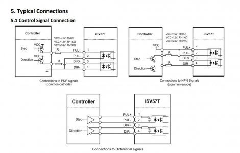
Inspired by James' testing of the integrated servo that cost only $100 I bought one but can't seem to figure out exactly how to wire that motor up. I realize that the enable pin will not be used, but I am not sure how to deal with the DIR + connection on the motor. I have read through the documentation to the extent of my ability and tried to zoom in and see how James wired it in the video, but don't want to let any more magic smoke out as I complete this project. He appears to have some of the pins jumped in the video but it is hard to tell.
The only possible matches I can find are:
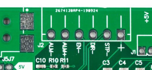
STP -> PUL-
"+" -> PUL+
DIR- -> DIR-
ALM+ -> ALM+
ALM- -> ALM-
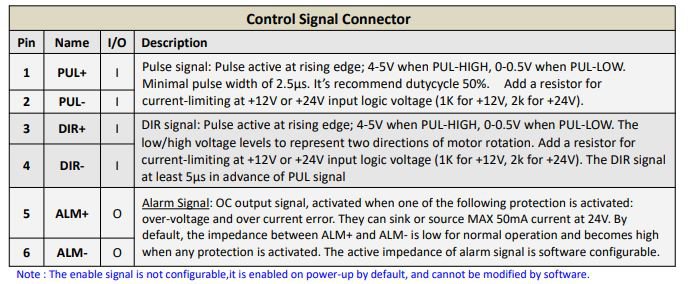
I may be way off here. Has anyone else wired this up (well, I know James did)? If you would be so kind, could you give me some information on the correct way to wire this? One image is from the manual showing the connections and the other is the Clough 42 board.
Thanks
Tom
Inspired by James' testing of the integrated servo that cost only $100 I bought one but can't seem to figure out exactly how to wire that motor up. I realize that the enable pin will not be used, but I am not sure how to deal with the DIR + connection on the motor. I have read through the documentation to the extent of my ability and tried to zoom in and see how James wired it in the video, but don't want to let any more magic smoke out as I complete this project. He appears to have some of the pins jumped in the video but it is hard to tell.
The only possible matches I can find are:
STP -> PUL-
"+" -> PUL+
DIR- -> DIR-
ALM+ -> ALM+
ALM- -> ALM-
I may be way off here. Has anyone else wired this up (well, I know James did)? If you would be so kind, could you give me some information on the correct way to wire this? One image is from the manual showing the connections and the other is the Clough 42 board.
Thanks
Tom