Needing more than a spark test?

I have two 2032 coin cell holders I could use, or two 18650 cells. The 2032's seem to run around 3V, whereas the 18650's fully charged are 4.2V each. Coin cells are a lot more compact! So ~ 6V vs 8.4V. The coin cells are a bit safer. Probably use them for the bias. Might use the 8.4V for powering the unit. Got to figure out how to shutdown the switcher first.
You can remove it's power connection. Alternatively, you might use a scriber, or a compass end, and repeatedly stab it until it stops.
More practical is to remove the L1 inductor, and remove R20. You can connect your bias battery to one end of C20. The 100K of R3 should mean that inadvertent forward bias would not hurt anything. The 9V supply comes off that same switcher, though it is post-regulated by U2. That means you need an alternative 9V, except you don't. It can as easily be 5V, or 2.5V.

For long term good behavior of a battery with only a tiny current of nA going out, I would use the lithium, but if you have some other batteries available, that's OK. The main property it needs is just to be a battery.

In that circuit, the "negative" supply is 0V, and the LMC662s are operated between that and +9V. The resistor chain R1, R15, R16, R2, offset the signal, to go through the opamps without crashing the rail. The simulations show that it fails to do this.
 
Last edited:
You can remove it's power connection. Alternatively, you might use a scriber, or a compass end, and repeatedly stab it until it stops.
My goodness! Think it might be easier to figure out the shutdown pin... It's there for a reason, I suppose. If the shutdown pin is grounded the switcher turns off.

However, that rework would be harder than removing the switcher itself. The switcher U4 is a SOT-23, which looks easier to remove than the inductor. Guess I will also have to remove the 9V regulator U2. I'm hoping I can use the hot air gun for this rework. I'll set it warm but low volume. Fortunately both parts are relatively far from the PIN diode.
 
I de-soldered the switching regulator using a combination of a solder sucker and solder wick. I have a stereomicroscope and one of those two-prong SMT-removing soldering irons that can be handy for this kind of surgery.

There is a path from the external power supply input through the inductor and a schottky diode in the switcher circuitry to the linear regulator so it's not necessary to replace the linear regulator, unless you replace the LMC662 wtih a lower voltage opamp.

On a different subject, I have added the ADC and buffer amp to my ADC board. Hand soldering that 48 pin QFP was a PITA -- gotta think of something better for the next time, that's for sure. Now I need to write some driver code to test it out.

I also swapped out the LMC662's on my signal conditioning board and did a few additional improvements. Now the output doesn't clip @ 2.5V. I _think_ the MCA spectrum looks better but I need to run a couple of different samples through the setup to see how things really look.
 
My goodness! Think it might be easier to figure out the shutdown pin... It's there for a reason, I suppose. If the shutdown pin is grounded the switcher turns off.

However, that rework would be harder than removing the switcher itself. The switcher U4 is a SOT-23, which looks easier to remove than the inductor. Guess I will also have to remove the 9V regulator U2. I'm hoping I can use the hot air gun for this rework. I'll set it warm but low volume. Fortunately both parts are relatively far from the PIN diode.
Somewhere far back in this thread, I described the "Polish coil wire trick" used for desoldering the legs of small outline ICs like SOT23 or SO8 or SO-just-about-anything. The enameled wire needs to be thin, maybe 26 AWG. I used some from an ex-relay. You thread the wire under the pins along the edge of the IC body, and find someplace out the other end to wrap it a bit, or in some way secure it. Then, one pin at a time, heat the pin while pulling gently on the (other end of the) wire sideways, at an angle to the pin, but as near as possible low down parallel to the PCB. The pin lifts, and the coil wire pulls through between the pin and the pad, snagging on the next pin.

One by one, the pins ping up. If you do it right, the pins apppear to remain unharmed. I use a small forceps to hang onto the coil wire. It's better to go to the second last corner pin, then put a little pressure under the IC, heat the last pin, and let it lift off. Some ICs I lifted this way "got launched", and might end up in a vacuum cleaner some day.
 
Last edited:
I also swapped out the LMC662's on my signal conditioning board and did a few additional improvements. Now the output doesn't clip @ 2.5V. I _think_ the MCA spectrum looks better but I need to run a couple of different samples through the setup to see how things really look.
In making a signal for the ADC, would not clipping at 2.5V be considered a "desirable" feature? My whole circuit deliberately uses 2.5V just so that is guaranteed to happen.
 
My supply of lead may be gone!
The roll of lead flashing I kept in a bucket got put in the neighbor's barn, along with his pile of recycle dead batteries. Then, at some stage, when the price of metal, especially lead, went up through the roof, one of the guys there went through the place looking for such stuff, copper, etc. :(

Things did get very bad here, with major thefts from church roofs happening. Now, if anybody brings lead to a scrap metal merchant, he wants your identity with address. He will take a photo of you. You sign a form. This is because the metal trade cannot sell it on without being able to prove where he got it from, and the trader faces charges of handling stolen goods. Some thief cannot simply fence the haul at a scrap merchant's place.

I think new metal sold has some sort of "tracer" ID in it.
 
Last edited:
My supply of lead may be gone!
The roll of lead flashing I kept in a bucket got put in the neighbor's barn, along with his pile of recycle dead batteries. Then, at some stage, when the price of metal, especially lead, went up through the roof, one of the guys there went through the place looking for such stuff, copper, etc. :(

Things did get very bad here, with major thefts from church roofs happening. Now, if anybody brings lead to a scrap metal merchant, he wants your identity with address. He will take a photo of you. You sign a form. This is because the metal trade cannot sell it on without being able to prove where he got it from, and the trader faces charges of handling stolen goods. Some thief cannot simply fence the haul at a scrap merchant's place.

I think new metal sold has some sort of "tracer" ID in it.
Sorry about the theft. Stinks when that happens. Like being violated.

Around here, scrappers have required ID for quite a while, at least 15 years. When I was at one I saw the scrapper turn away a pickup truck full of stuff because they didn't have ID. Of course they should have called the police, because they should have had a driver's license between them, but that might have been bad for business.

In large 50lb quantities lead goes for about $2.40/lb. Roto metal wants $139/55lbs, except there's a $150 minimum for free shipping. 5lbs of lead ingots gets you to $150. We don't miss our scrap until it is gone.
 
Somewhere far back in this thread, I described the "Polish coil wire trick" used for desoldering the legs of small outline ICs like SOT23 or SO8 or SO-just-about-anything. The enameled wire needs to be thin, maybe 26 AWG. I used some from an ex-relay. You thread the wire under the pins along the edge of the IC body, and find someplace out the other end to wrap it a bit, or in some way secure it. Then, one pin at a time, heat the pin while pulling gently on the (other end of the) wire sideways, at an angle to the pin, but as near as possible low down parallel to the PCB. The pin lifts, and the coil wire pulls through between the pin and the pad, snagging on the next pin.

One by one, the pins ping up. If you do it right, the pins apppear to remain unharmed. I use a small forceps to hang onto the coil wire. It's better to go to the second last corner pin, then put a little pressure under the IC, heat the last pin, and let it lift off. Some ICs I lifted this way "got launched", and might end up in a vacuum cleaner some day.
I will try that. Have to look around for some magnet wire. I have bare wire, that probably won't do, and some solder able magnet wire which is handy for rework. Solder temperatures will displace the insulation. Got to look for the normal magnet wire! The stuff you have to scrape.
 
I will try that. Have to look around for some magnet wire. I have bare wire, that probably won't do, and some solder able magnet wire which is handy for rework. Solder temperatures will displace the insulation. Got to look for the normal magnet wire! The stuff you have to scrape.
The thin magnet wire used for relays does work, and that kind does give up it's varnish in a toxic mess and fumes when one is deliberately trying to tin one end.

I guess that stuff called "SpeedWire" that comes in little bobbins with a pencil-type dispenser, sometimes used for casual digital prototyping is maybe not the sort you need, because that one has varnish designed to solder through easily, but it may well work anyway. The magnet wire that has to be scraped is obviously ideal, but I found I did not have to go to those lengths. Pulling through under a IC leg is not the same as being aggressively heated in the middle of a fluxed blob of molten 60/40.

Just find any very thin coil wire, and try it. It works surprisingly easily. Don't be too fussed about whether it needs scraping in normal use for connecting. Here, of course, we want the varnish to stay on. Old relays had the right stuff for me, but not automotive kind. Even if the varnish is a bit hurt, it still slides through under the pin, and none I tried ever ended up soldered to the wire.

The first I did was a 28-pin. It works better if you go along one side, and leave the last pin alone. Then start down the other side. This keeps the IC from tipping up until you are nearly done, and stops it from "rotating" when you get near second last on the other side. Then take out the last pin on that side. Now, stuck on only one pin, if you knock it or inadvertently tip up, it can pull up the last pad and tracking with it, so go careful. Now, heating the last pin from the top will let the IC come up, or fall off. Just a very low force encouragement (I used a toothpick), while heating, and it comes off.

Then finally, solder braid and flux + IPA wipe cleans up the pads.
 
Last edited:
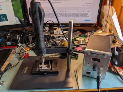
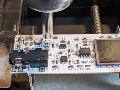
Just for my personal amusement, I tried removing the switcher IC U4 with hot air. I put on a 4mm nozzle and used a stand to hold the air gun at the right height, about 4mm off the surface of the PCB. The nozzle is about the size of the part. I set the air temp and used the lowest flow setting. Within moments of sliding the board under the air gun, the solder had melted on all of the part pads. I moved the part aside with tweezers. Was able to pick up the switcher and not have it fly away! Whole operation took a few seconds. All other parts on the board stayed where they were. Much easier than any other way that I have tried. That was painless! If you look carefully you can see the switcher on the plate stand, by the corner of the PCB vise.

I had bought a full set of nozzles for this hot air gun, going down to 2mm in diameter. That size ought to be perfect for 0402's if I need to go there. Of course with an 0402 they are easy to remove, just touch an iron to it and the part sticks to the iron. 0402's are a lot harder to solder. For that, I'd try this 2mm nozzle. Definitely recommend using hot air for this, quite fast. The downside is you can't use a microscope because the hot air gun is in the way! Looking at the pads, I do not need to remove the solder, unless I'm going to put the switcher back.
PXL_20230126_154451228.jpgPXL_20230126_155001979.jpg
Now if I solder a connection to the back side test point PDV, I can bias the PIN. Since the inductor L1 and D10A are in place, I can power the board from the P3 pads. I will try using 12V. That will bias the PIN to a value under 12V, maybe 10V. I will check that. But as long as VPD is greater than that value, the diode D3 will be back biased. So this means I need something greater than 12V for the second supply. For the moment I am trying to maintain the existing circuitry until there's an obvious path forward. Still trying to get my feet wet without totally falling it!

FWIW, I got the hot air gun from AliExpress, a spare heating element and extra nozzle kit for a very favorable price. I think I bought the adequate, but not good stand from Amazon. Very worthwhile if one is doing SMD work.

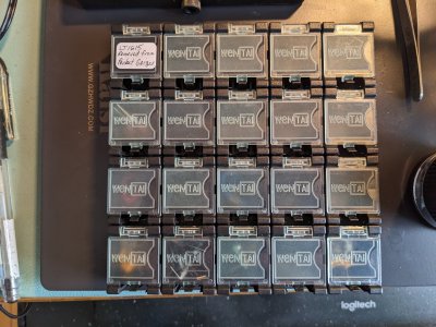
Another recommended purchase is to get ESD safe SMD containers. They lock together. The ones I have are made by WenTai. I put a tag on a spare box and labeled it LT1615 "removed from Pocket Geiger". The boxes are about 25mm x 25mm x 22mm high. Great for storing SMD devices.
This is my miscellaneous box, and hasn't been sorted. Basically junk on the bottom row! Hmm, found an LT6238 there, which is a decent part.
PXL_20230126_162136561.jpg
 
Back
Top