Needing more than a spark test?

The copper foil is wrapped around the detector, and probably is used to stop alpha particles. I don't see an electrical connection to it, so it probably is not a shield to reduce electrical noise pickup.
While you will most often see a shield connected to a circuit ground at one point only (if it's any good), it not being connected at all does not stop it acting as a Faraday shield, and many may be deliberately so, depending on all sorts of things.

Any external field cannot exist beyond the short circuit boundary condition of the copper. Inside that copper cover, they cannot exist, save for a small amount near the "entrance". The diode is the possible receiver of a multitude of high level RF, from Wi-Fi, phones, radar, everything. Distinguish between RF, once it has become propagating EM, (like light), and the real near field precursors (magnetic, and electric). The field from a power line is huge. Even the (50Hz) field from my house wiring is so strong it maxes the screen on my scope if I touch the end of a probe, and it won't go away entirely if I put my other hand on the scope chassis.

For some measurements, the only way to lose the unwanted noise is to use two probes, one subtracting in differential mode.

While I have not yet read up in detail, (and my "radiation lab experiments" budget got hijacked), I am considering one of these also. As I understand what was said before, this device responds to input energy in the X-Ray region directly, instead of needing a scintillator material to down-convert to visible light frequencies, and work like a regular photodiode.

From it's application description, it would seem to be used in "Geiger counter" mode. That concerns a little, because we want a preserved pulse maximum amplitude. Geiger counter pulse makers often use comparator thresholds, followed by lots of non-linear gain, to make the loud click pulse. Excellent that you have untangled it enough to check this out in simulation.

You are right about the "distractions". The next is accounts, and the (ugh!) paying of taxes. I have worked up a lot of aerobic digging under the tree stump interfering with my future shop hardstand. So far - about 30% of the big roots "disconnected". The darn thing (tree) still feels more solid than my left side lathe support block! It gives a negative blend to the phrase "My Lathe Rocks"!
 
Info I found on First-Sensor's web site indicates the detector is a PIN diode, not an APD. Also, their leakage current vs. bias voltage curve shows that the device isn't anywhere close to its avalanche breakdown. The Pocket Geiger design has two comparators to turn the analog signal into pulses -- one is set to generate the "noise" signal and the other, with a higher threshold point, detects a real particle/photon event. So the detector itself is not operating in a geiger mode, it's linear. That is the only reason I went forward with buying one of these.

Regarding the shield issue, I guess I will find out. But the whole thing is going to be inside a rather substantial lead box anyway. Parts of it will actually have two layers of shielding, since I want to shield myself as well as the detector from the primary gamma rays. The skin depth of lead is greater than copper but 1/8" layers should attenuate even 60Hz EM fields by a substantial amount.

The other thing is, since copper's K-alpha line is 8.04Kev, it's possible that it could fluoresce and contribute a stray energy peak. It wouldn't be from the steel alloy metals, but I don't want to limit what this to just analyzing ferrous items. For instance, it could be handy if you collect antique jewelry -- silver's K-alpha is 22.1Kev, and gold's L-alpha line is 9.7Kev -- and copper is often added to silver and gold alloys.

Good luck on that stump. I've fought with 'em as well, and it's amazing how difficult it can be to remove them....unless you've got some big machinery to do it. Don't try pulling it by tying a rope to a vehicle -- the rope can stretch like a rubber band and when it breaks it can turn into a projectile. Even worse if part of the stump breaks and remains attached to the rope. I had a near-miss once and that was scary enough.
 
Slowly - slowly, I am getting into into circuits that make bloody high voltages. I am going to play with this (sensitive) PMT all the way to the end, but I have already decided that small, solid state, is better. It will be a PIN or a avalanche photo-diode route for a practical, low cost project gadget. The software display end will be much the same, so when I get the diode kit, it should not be too hard to apply it. If the PIN diode type is the winner - then yay - no scintillator!
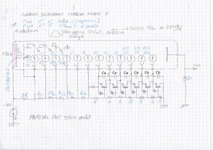
PMT SPICE!! - and it seems I don't know how to spell "dependent" :confused:

PMT SPICE ver0.01.jpeg

Reluctant tree stump has finally yielded. It was becoming my outside aerobics replacement. Cut up into chunks for the wood-burner next year. There is now a huge hole where it was, and I now realise how much top-earth I am going to have to remove before putting in some hard-core. Just out back is the neighbor's wheat crop. After it is harvested, which has to be soon, I can maybe borrow his tractor with the big scoop bucket in front, and clear the land for "chez workshop".

There seems still a never-ending list of "other" stuff needing doing, but I now ease into my "playtime" slot after 16:00, and get mixed up with South Bend(s), and sometimes, the nuclear chemistry!
 
I had trouble believing the adage that a tree's roots are about half the tree's total volume until I tried digging out a stump. Now I do!

I also thought I could pull the stump out using my (small) 23HP tractor. No dice -- the wheels just dug holes in the ground.....so I innoculated that one with some wood-eating fungi and let time do the heavy lifting. It took just one season and the roots turned into punk. Probably not what you want under a workshop, though!

A question about the bias string in your PMT SPICE model. Are the Ca's and Cb's parasitic caps or there to reduce "droop" due to current pulses traveling through the dynodes? I think I know the answer but best to not guess.
 
A question about the bias string in your PMT SPICE model. Are the Ca's and Cb's parasitic caps or there to reduce "droop" due to current pulses traveling through the dynodes? I think I know the answer but best to not guess.
Yes - the capacitors supply the electrons for the dynode signal, though not like "smoothing capacitors" for a conventional supply. The dynode current is supplied by the transistors, fed by the capacitors, and these are set between the dynodes, not taken to ground.

The rationale starts from the values of resistors to set suitable voltages, each relative to the next. If set low enough to supply electrons into the tube without the voltage collapsing, then one needs a (dangerous) amount of mA from a (hard to make) supply, and hot high wattage resistors. If the supply is a tiny thing, getting up a high voltage from a little switched-mode circuit, it is going to be high impedance. The chain will have typically meg-ohms in it.

Throw in the need to have a low value signal load resistor, because noise is √(kTBR) (V). A decent scintillation pulse will run many times more current than is available from the bias chain. Hence the need for some local energy storage for the last six stages.This is provided by 3 x Ca and 3 x Cb working with transistors that have a high Hfe gain. The secondary electrons flow through the successive dynodes, and into the collector of each transistor. The emitter potential of each transistor increases while the collector current decreases, along with the decrease in base current. At this point, the decrease in collector current is nearly equal to the current flowing through the photomultiplier tube. With very high gain RF-speed transistors, in this way, they supply the current for the PMT. The capacitors have to be high frequency types, and only large enough to supply the electrons to that single stage through the highest pulse, not the whole tube.

The circuit is a published one, developed by Fermi National Accelerator Laboratories. Our thanks to them.
This is code-speak for "I copied it from their handbook"! :)

We are not going to be shunting signal with capacitor-laden "filters" on the output in the cause of "losing noise".
Noise cannot be "lost" once it has contaminated the signal information. The electrodes are not like grids in a vacuum tube. They are more like a series of anodes. There is not direct "gain" from a dynode voltage change, only a tiny change in that stage gain. Even if there are volts of "noise" in the resistor chain, they should only fractionally change the accelerating voltage of any dynode in their noisy way, and end up supplying useful secondary electrons to the current pulse anyway.

The SPICE model allows to put a loud noise voltage source onto the supply - just so we can get curious about how to get the supply clean. My strategy is to use a very high frequency supply - maybe 2MHz or more. Making it clean then only requires much smaller capacitors and inductors. Come to that, if one makes the supply control loop bandwidth so fast that it can actively supply against some kinds of noise, you can say goodbye to 50Hz and 60Hz house fields and much other racket. One still has stop magnetic fields from modulating the electron stream.

I could be wrong about it, but so far, no crack-ups, flashes, smoke, bad smells or other untoward stuff yet.

There are some other features you can't see. Precautions to prevent any part of the chain voltage rising to do damage in case any part of the chain becomes open circuit. This gadget is allowed to fail, and it will do so gracefully.
 
Last edited:
With about 100V dynode-dynode voltage drops, that knocks a lot of RF transistors out of the running -- many have fairly low breakdown voltages. What devices do you have in mind for the purpose?
 
I did not see this as a problem. I admit that when I said "RF", I did not mean anything well into VHF/UHF.
I was hoping for something that would respond at a few MHz if the circuit gain was more than about 20.

Avoiding those that have gain minimums that start too low - e.g. Hfe = (40 - 140), we can select from (say) mouser.com. I suppose Digi-Key and other suppliers would have others, with overlap on some.

Setting the Vce > 120V, and the gain-bandwidth product fT = 100MHz -> 300MHz, there are 19 through hole types, and 57 SMD types. After that, we go by price.

Just looking at the very first one, £0.209 each if you buy 10.
RHOM 2SC4102U3HZG has BVceo = 120V, and it can run 50mA (do we need more?)
The gain hFE (min) = 180, and hFE(max) = 560, and fT = 140MHz (typ)

If 50MHz is enough, and hFE 50-150 is enough, then Diodes Incorporated ZETEX FMMT459QTA SOT-23 package lets you have Vceo=500V. Slower, and it costs £0.379 each if you order 10

I tried again on ROHM for the 2SCR375P5T100Q 120V 1.5A (but not simultaneously in a SOT-23 package).
If it were asked to deliver 5mA with the whole 100V across it, it would be trying to do 500mW of getting hot.
But.. it does not have to, unless there is a blizzard of pulses so fast it is on all the time.
This one has gain 120 - 390, fT = 200MHz, and it costs £0.376 each of you buy 10.

I am thinking there is probably a sweet choice somewhere among the 76 we can see already, after we eliminate the way-too-expensives, and the low gains, and the gets-too-hots, and the goes-too-slows, but at a pinch, that last 200MHz thing would have a chance.

I am happy to run with any reasonable cost suggestion anyone might have.


OK, not talking about GHz here -- that opens up your options quite a bit.

You might be able to narrow the search by looking at the collector current needed to achieve Ftmax. If the transistor needs 100mA to get there, you won't get full speed out of it at Ic=100uA. Choosing a transistor with the highest-possible Ftmax that has a BVCES > 100V would be the best (but perhaps the most expensive) way to ensure you have sufficient BW in this application.

I don't know if the transistor models available from LTSpice include this Ft variation vs Ic or not. Hopefully they do, otherwise it's not very useful for RF designs using BJT's.

Something else to think about: higher collector currents will increase the current flowing through ALL the resistors in the string. So if your supply is 1200V and it needs to supply 5mA that's 6 watts. If you split the bias string in two, the all-passive portion can use much less current. 600V * 5mA = 3W, a bit nicer (but still dangerous if you happen to get across it).

However, 5mA probably is overkill. The data sheet for the Rohm part you mentioned (RHOM 2SC4102U3HZG) gives a typical value of 80MHz @1mA, 'way down from its maximum -- but probably good enough (see Figure 8 in the DS). Still, you still would be looking at a HV supply capable of sourcing 1.2W. If you can find a transistor that still has decent Ft at Ic = 100uA that will make things even easier. The fact that the Ca's and Cb's can provide the transient current needed (and so the transistor Ft's will transiently go up) means my back-of-the-napkin "design" is a worst-case scenario. So there's some good news there :) .
 
OK, not talking about GHz here -- that opens up your options quite a bit.

However, 5mA probably is overkill. The data sheet for the Rohm part you mentioned (RHOM 2SC4102U3HZG) gives a typical value of 80MHz @1mA, 'way down from its maximum -- but probably good enough (see Figure 8 in the DS). Still, you still would be looking at a HV supply capable of sourcing 1.2W. If you can find a transistor that still has decent Ft at Ic = 100uA that will make things even easier. The fact that the Ca's and Cb's can provide the transient current needed (and so the transistor Ft's will transiently go up) means my back-of-the-napkin "design" is a worst-case scenario. So there's some good news there :) .
So far, I have been meddling with LT switcher circuits. Turning the mind to the PMT chain, I was after getting something good, freely grabbing at circuits that took decades to emerge, even though the end circuit looks relatively simple.

The way those transistors work is elegant, looking simple, but not really so, with a diode bias. The voltage between dynodes is being "regulated" in a way that does not, I think, require a big linear quiescent current. All in series, with perhaps a relatively tiny collector current overall, each sitting there with a local capacitor energy store, ready to deliver.

The resistor chain can be high impedance (again - I think). When the pulse comes, and the voltage (tries to) change, the transistor turns more on, and the gain goes up as the collector current goes up, and wham, the transistor replaces the electrons being sucked off the dynode. I think they all pretty much act together. The transit time between dynodes is tiny.

It is because I did not fully understand how this happens that I thought the SPICE model would help. A current-controlled current source handily models secondary electron emission. Models for the transistors have been the norm for decades. If not available from the website (usually they are), you can get the values from the datasheet, and plug in. Transistor models are normally mathematical functions, for done speed, instead of being included as sub-circuits. Full sub-circuit modeling every internal bulk resistance, capacitance, etc. is done, but we obviously like the speed of the mathematical equivalent.

So far as I know, fT is catered for. In the transistor hybrid model, there are input and output parasitic capacitances, and a "Miller" capacitance CjBC. These, along with transit time, delivers the gain-bandwidth product fT, though that is not the fast way. Normally, one does not have to do any of this. If the transistor SPICE model is available, you don't have to mess with datasheet entries to contrive your own, and they do show the frequency roll-off.

If the SPICE model hangs me up for too long, I will simply build the circuit, (and maybe watch it fry)!

In the last couple of days, it has been hot and dry, so the monster combine has been out there, and the view to the North is transformed. Harvested, and all the straw in big rolled up bales. I can't believe it is already August. This has been a very strange year so far!
 
Last edited:
Back
Top