New Member From Langley Bc Ready To Start Lathe & Mill Shopping

Given that I"m 5 -5 on a good day ( thanks to some rather severe compression fractures in the lumbar and thoracic spine which results in my GROSSLY overestimating my skill on a motorcycle on more than one occasion) I might not find that a good position. Once I have the mill in place it will be a bit easier to decide I guess. The location Chevy used seems really convenient if a bit exposed so might work better for me. Thanks for the tip on the tach, I'll have to go back thru Mark's post on that and have a look at the actual mill before I order a tach.
Alex
 
A little more progress to report on the lathe.

I finally got around to tackling the lathe wiring.

This looks so nice from the factory, a pity to pull it all out but that's what I did.

QczkvLoC_o.jpg


fwvJShD1_o.jpg


Not so pretty any more.

bqHSPxy9_o.jpg


The new layout, figuring where everything goes.

rD5q3EvU_o.jpg


A close up of the VFD setup, very similar to the Mill layout.

QtNvi70t_o.jpg
 
Another weekend is almost done and I've managed to get a little bit of time in the shop today.

I've finished the VFD enclosure and mounted it on the end of the lathe, here it is.

9YLlZtAq_o.jpg


Here's a shot from the inside.

DEDCxPHK_o.jpg


After wiring up the fan in the Mill VFD I decided to install an ON/OFF switch on this box as the fan is VERY LOUD when nothing else is going on in the shop. I may try running it on 12VDC and it should run a bit slower and quieter.

I'll need to figure out how to have the fan only run when the lathe is running and then I shouldn't hear it.

I put the switch out of the way between the intake and exhaust ports.

tfuo73rs_o.jpg
 
Last edited:
My Teco VFD has an output that comes on when the motor is in use. I use it to prevent accidental switching between the mill and the lathe while either one is running, and to turn on a red or a green LED to indicate that status. Maybe there is a similar output on yours.
 
My Teco VFD has an output that comes on when the motor is in use. I use it to prevent accidental switching between the mill and the lathe while either one is running, and to turn on a red or a green LED to indicate that status. Maybe there is a similar output on yours.

Thanks Mike, that's a good idea, I'll check the manual or failing that I know someone who may know already.

David.
 
Wish I had more progress to report but I had a few days of fun stuff with the family this Canada Day long weekend and didn't get much done on the machines.

I've been looking at the wiring diagrams provided by Mark Jacobs until I start seeing them in my sleep but I'm still not fully understanding them.

I could just wire them up as per the diagram but I do really want to follow the logic so I can actually verify my work if something doesn't work right.

The challenge is the diagram versus the way I've placed my actual components are not alike.

I have the relays in the existing small cabinet at the back of the lathe and the VFD and 24VDC power supply are in the larger lower cabinet.

I need to run an additional set of cables between the two boxes to complete the connections, but I don't have any extra shielded cable so I was trying to see if I could use what I have available to me but it doesn't look like it's possible.

Anyways I got started on the relays and terminal strip and have flip flopped on keeping the factory supplied main power disconnect in the existing cabinet or adding a new one which I already bought and install it on the VFD box like I did on the mill.

Both options have their merits but I think I may go ahead and add one to the VFD box as that was my original plan and I won't have to deal with the limited space for wiring in the smaller box and I'd also only have 24VDC in that box and keeps everything a bit cleaner.

Here's where I'm at so far with the wiring, I will tidy this up a bit before it get all buttoned up.

BTW those 2 circuit modules in the top of the picture are not part of the build, they are the control boards from Kaba Saflok Hotel Card Readers, I'm modifying them for a job so they will fit on a single gang plate.

HNrnj1OM_o.jpg
 
You do not need to use shielded cable for short runs of wiring. The cabling and components are in modules, almost all my current lathe builds have a separate VFD enclosure with the high voltage components and I use the stock lathe enclosure for the logic control. The important concept is that there are relay contacts specific to the VFD input signaling vs. 24VDC which controls the relay coil logic. If you have any questions shoot me a PM.

On the fan, I will often use a triggered timer, so when either the forward/reverse relays are active it sends a run signal to a relay to close which sets the run time, or you add an extra set of relay contacts (3P relay) and use the 3rd pole to turn on/off the fan. Another alternative is to just use a cabinet thermostat to turn on/off the external cooling fan based on temperature. https://www.ebay.com/p/Kts011-0-60-...ostat-Sensor-Temperature-Controller/508529142
 
Mark, thanks for the quick response, I've ordered a couple of those cabinet thermostats, at about $3 each including shipping it was a tough call but I went ahead and ordered them. :)

Nice to know I don't need shielded cable, that will allow me to get on with the rest of the wiring without waiting for another shipment.

One quick question, I've purchased a proximity sensor kit and I see on many of your lathe builds there is a button for proximity override, why would you want to override the proximity stop sensor?

I'll email you once I've figured out what other questions I may have.

David.
 
Wow, over 2 years since I started this thread and what a slow poke I've been in getting my machines finished.

I did get the lathe some what operational last week but still need to finish up a few controls and the DRO installation.

To be fair, I bought these machines earlier than I intended and wanted them to be ready once I freed myself up from full time work to get some long over due projects done, so from that perspective I'm still on track. haha.

Here is my son John finishing up the VFD programming, seems everything is working and he ran it through a few test sequences.

IMG_0981_zpsm0rmrpix.jpg

Here is the relay control box during the planning stages, I used one of the factory liquid tight flex conduits to route the wiring around to the front control pod, a little tight but worked OK.
IMG_0983_zpsoiybrf0d.jpg
 
I guess I should update this thread so the journey is complete.

I've have had my PM 935 mill up and running for sometime, but I still need to complete the tach install, build a proper stand and buy a better vise (or maybe 2)

The lathe on the other hand sat neglected as life got busy and I've been distracted by work, family, motorcycle trips and just living life.

Sometime around Dec 1st last year, I got a list of things together that were incomplete in my life and started working on them, the lathe was on the list but it's taken till this month to get at it with a dedicated recommitment.

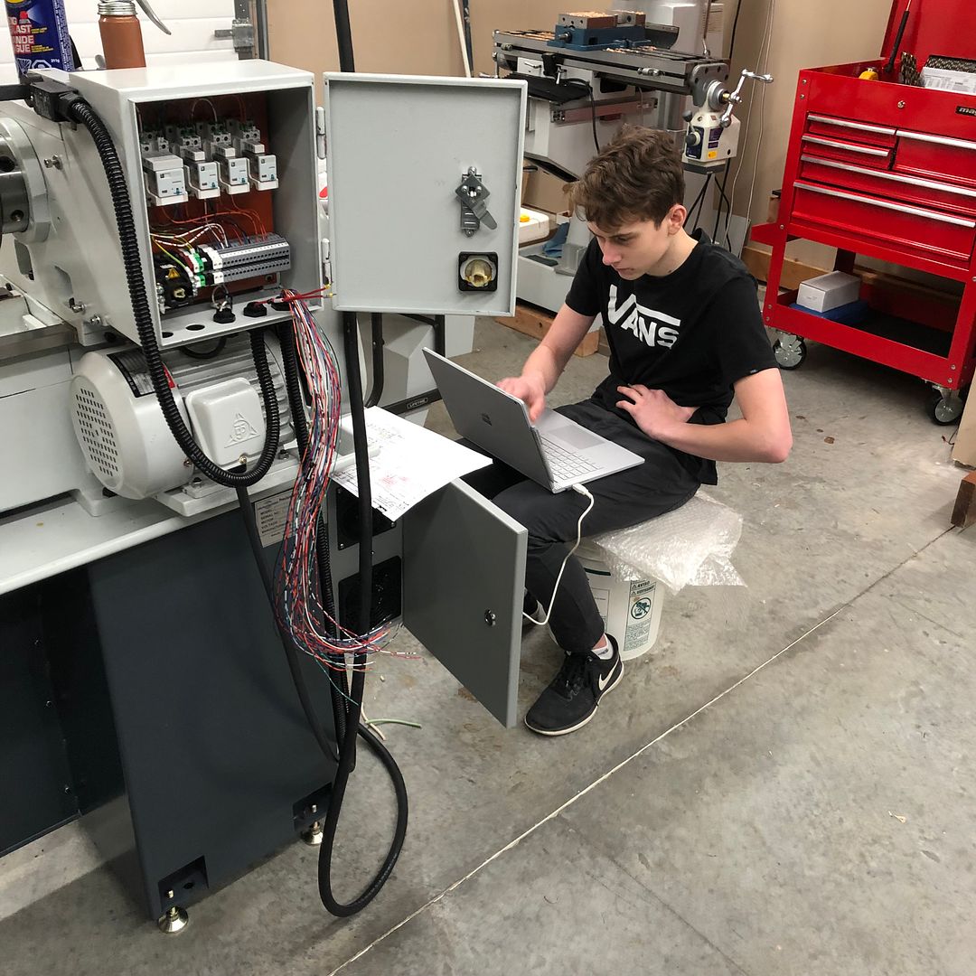
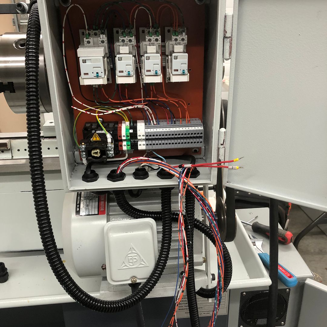
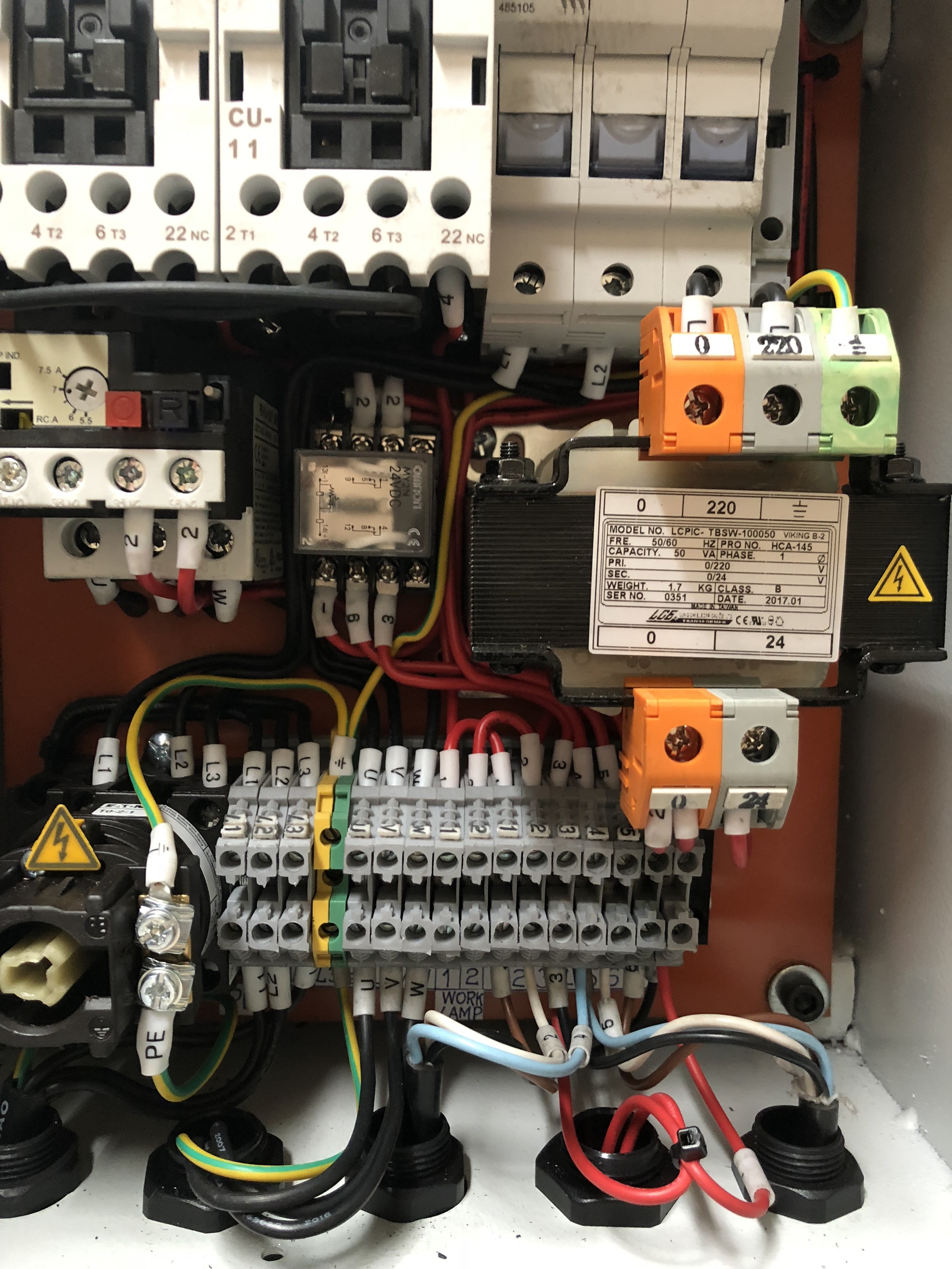
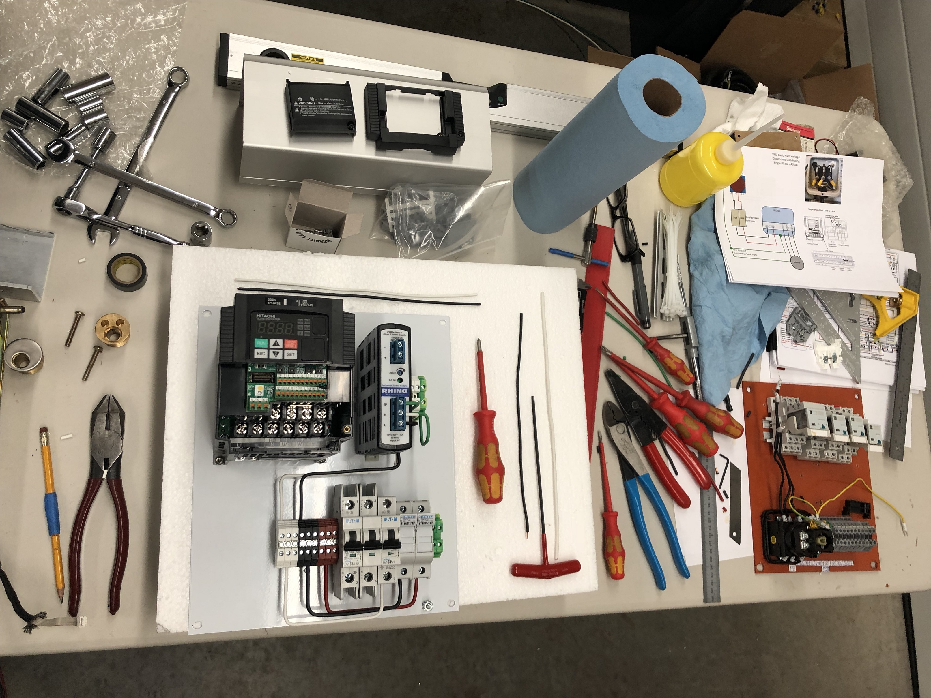
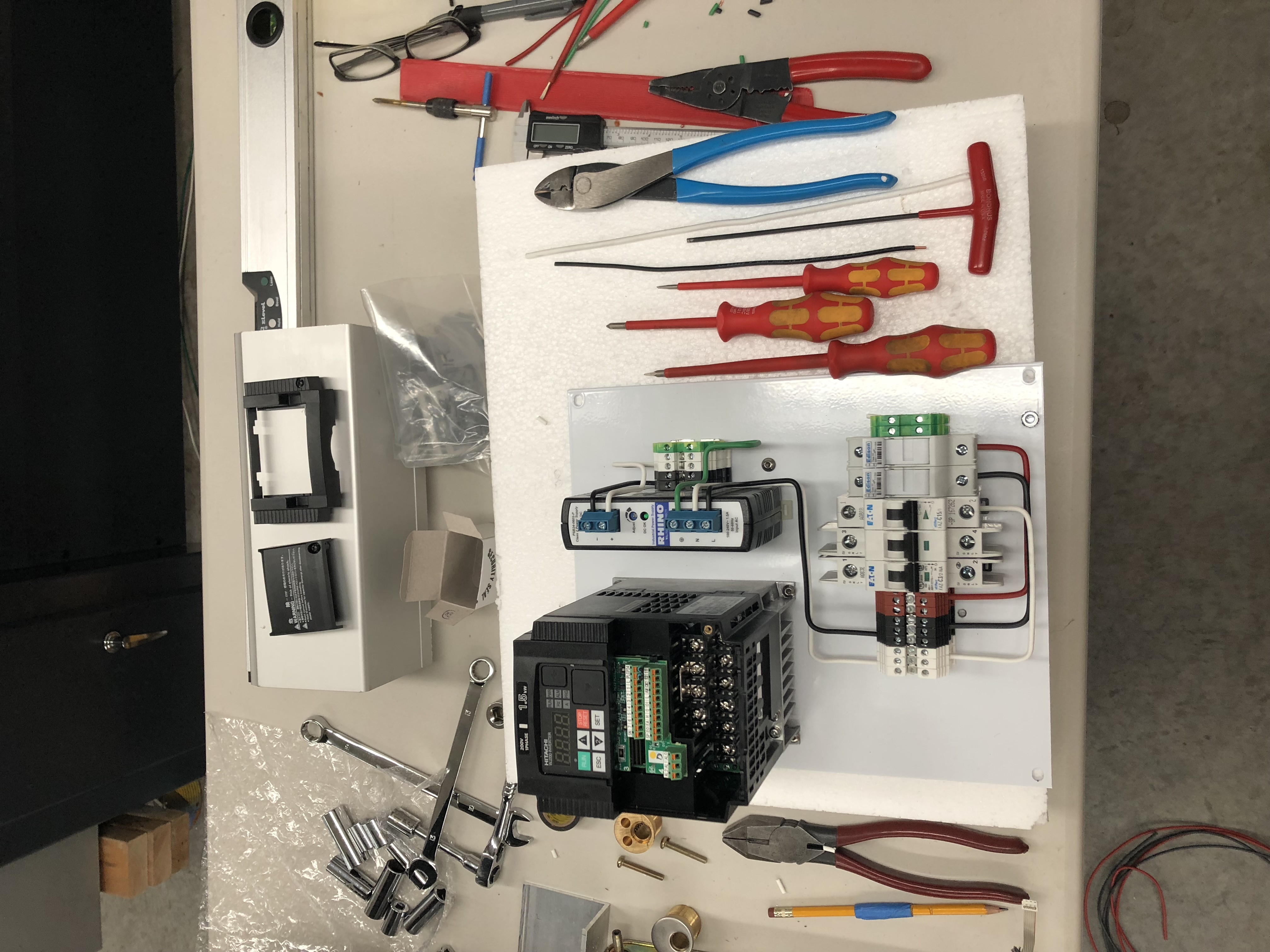
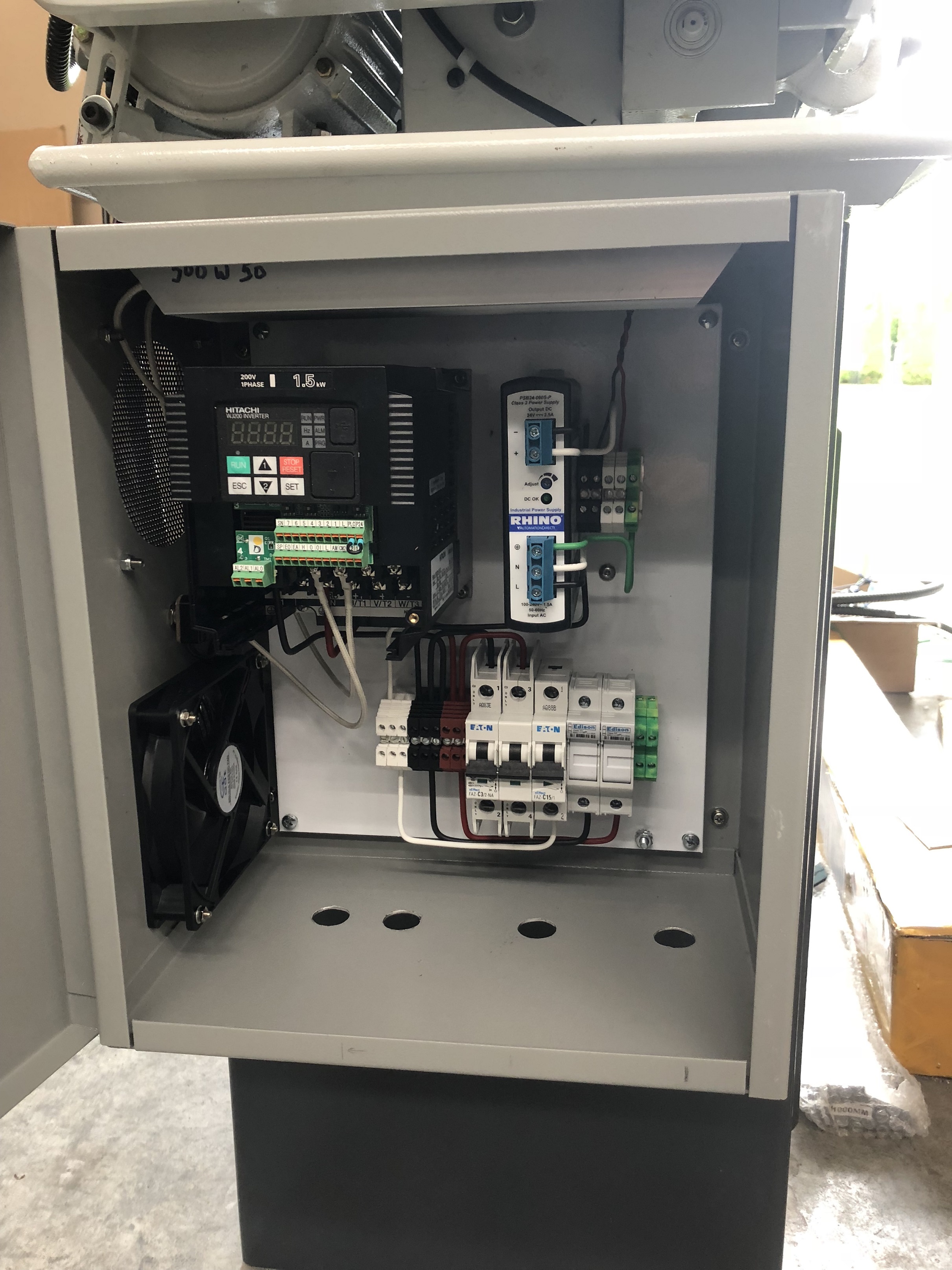
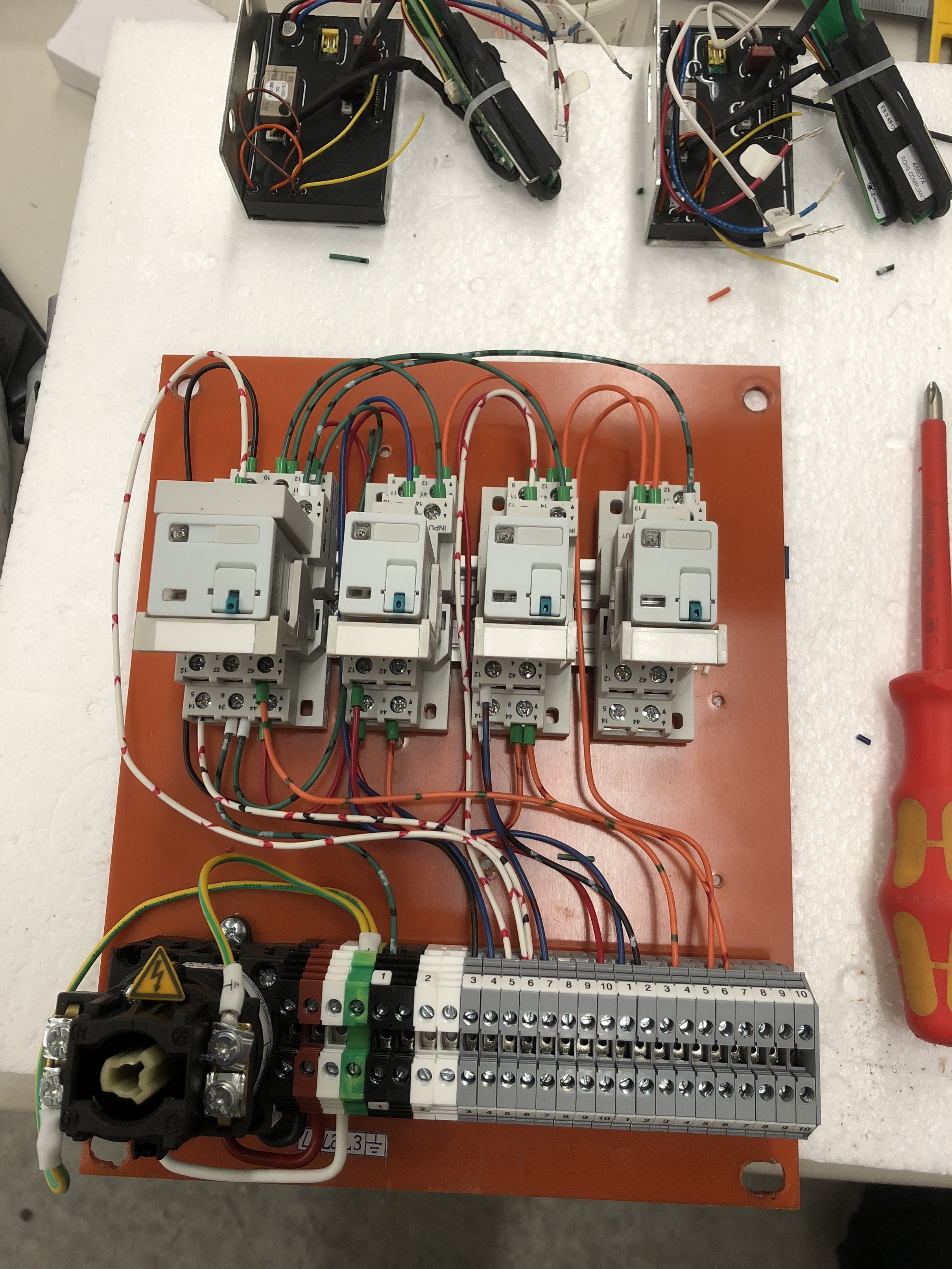
I studied the wiring diagram supplied by Mark Jacobs and finished up the wiring, surprisingly everything worked perfectly which was a nice feeling as it`s easy to get a diode installed backwards or miss a vital connection as I did on the mill install.

The electronic braking is outstanding, I just love that feature, also the forward reverse jog is cool.

I installed the Aloris QCTP, I took my time milling the supplied material for the T-nut and fitted it, very nice piece of kit and it works so smoothly.

IMG_2082.JPG


Last week I was working on mounting the DRO including the Easson display, I made a few mockups for the display and wasn`t happy with any of them, they just looked cobbled together, functional but not easy on the eyes.

On the mill I used the factory supplied bracket and arm for the display and it looks OK, but I wanted to do something better on the lathe, so I found some 1.125 aluminum round and machined a flat on one side then drilled and tapped 3 holes using the DRO line feature.

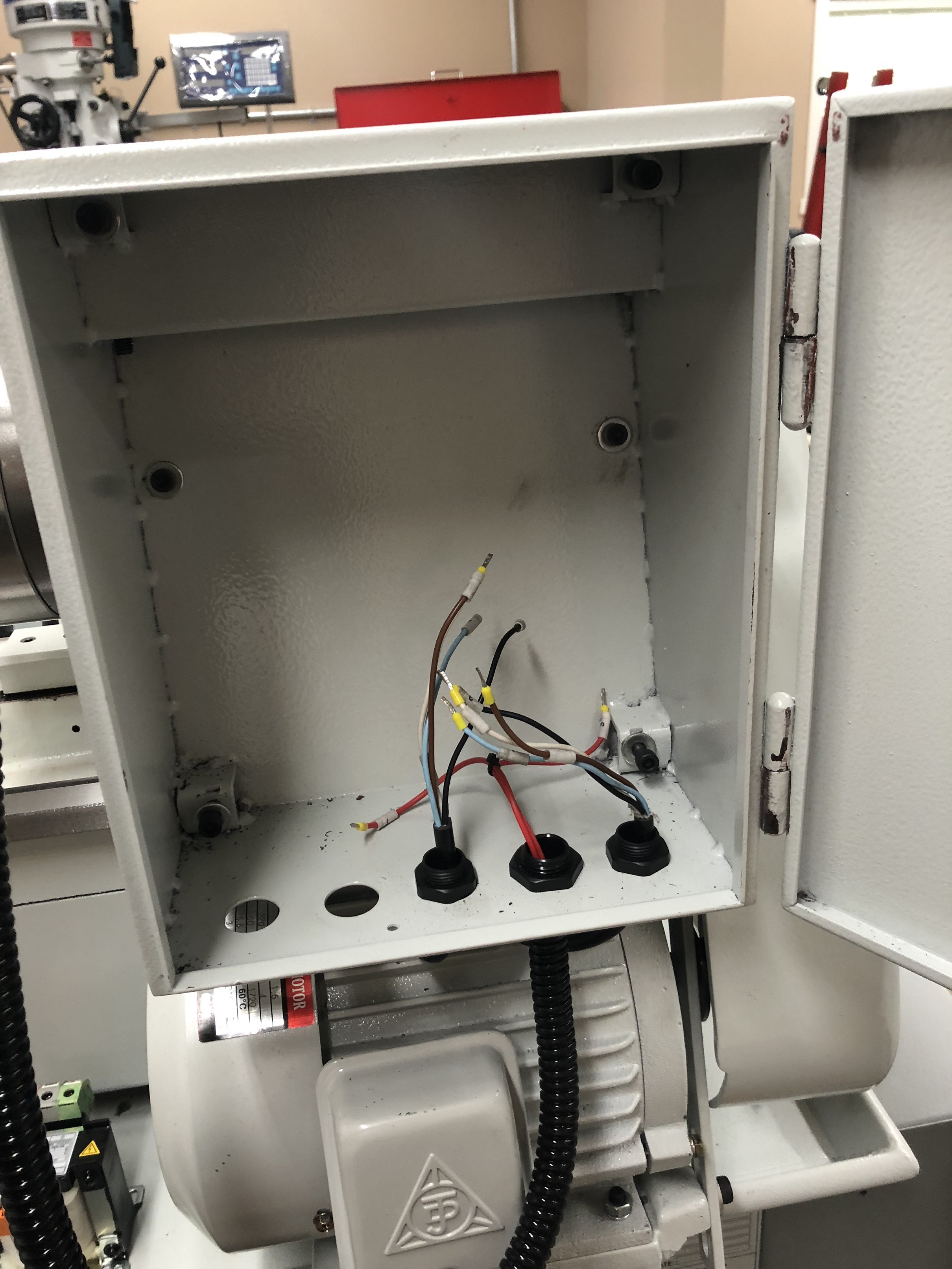
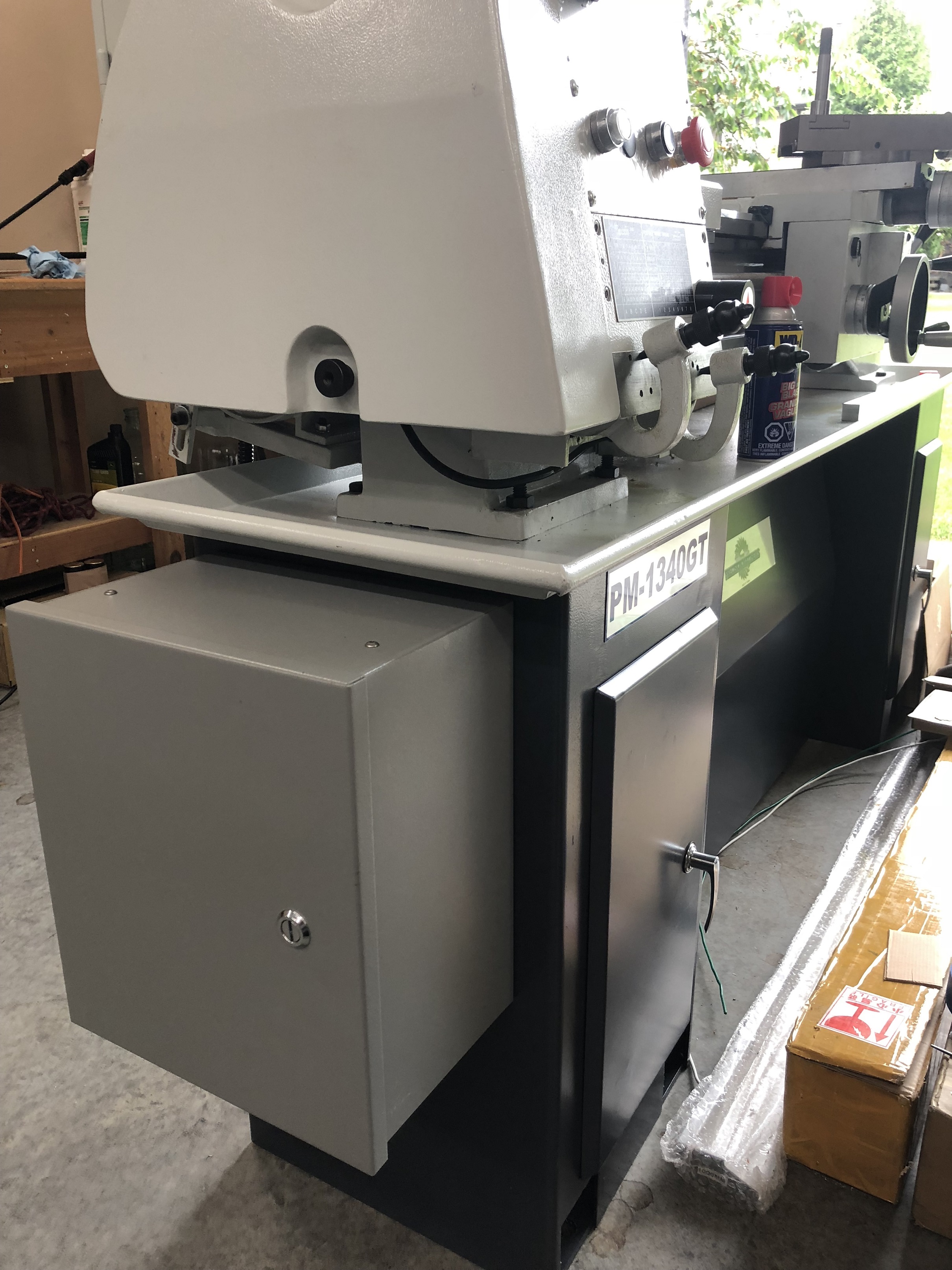
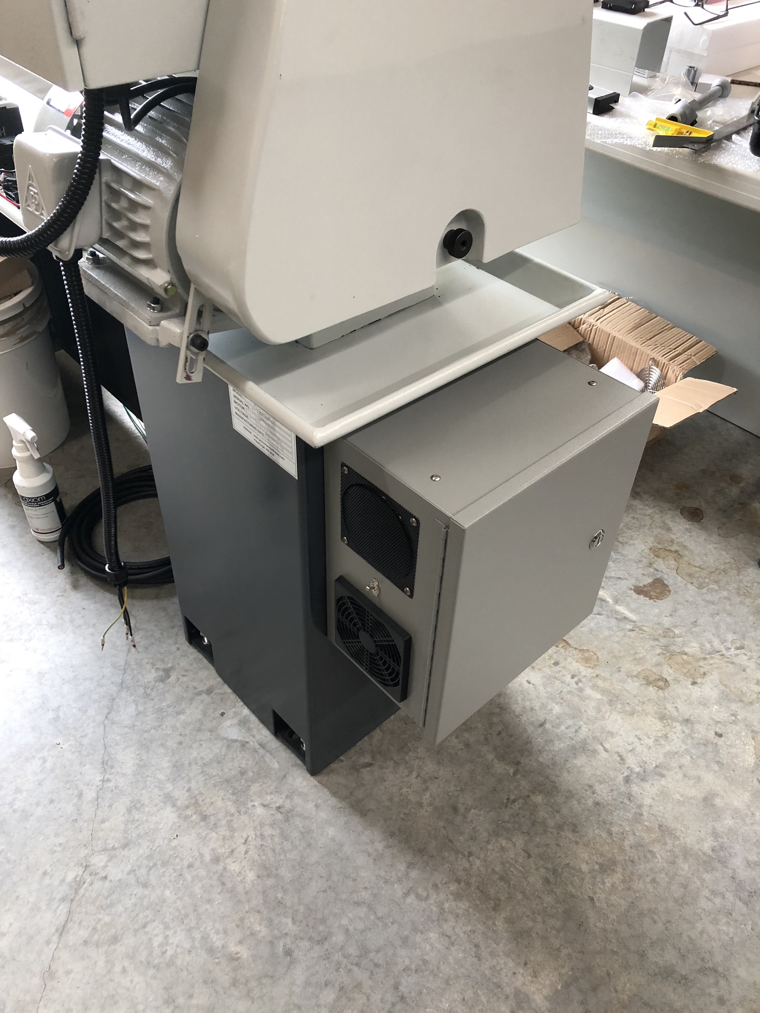
I used the same settings to make a template for drilling the side of the electrical box, clamped to the box and drilled 3 holes, once installed on the electrical box I considered how to mount the arm, and then I thought do I actually need an adjustable arm, maybe not.

So I drilled the center of the piece out using the lathe for the first time and then tapped it with a 10 X 1.5 tap, using the lathe turning the chuck with the jog button, that was easy.

After test fitting it the display sat up quite high so I drilled out about 1`` of the threads out so it could thread in further and the display sat lower, it tightened up in the exact right spot and I left it like that till I pull it apart for painting.

IMG_2080.JPG


IMG_2087.JPG


IMG_2086.JPG


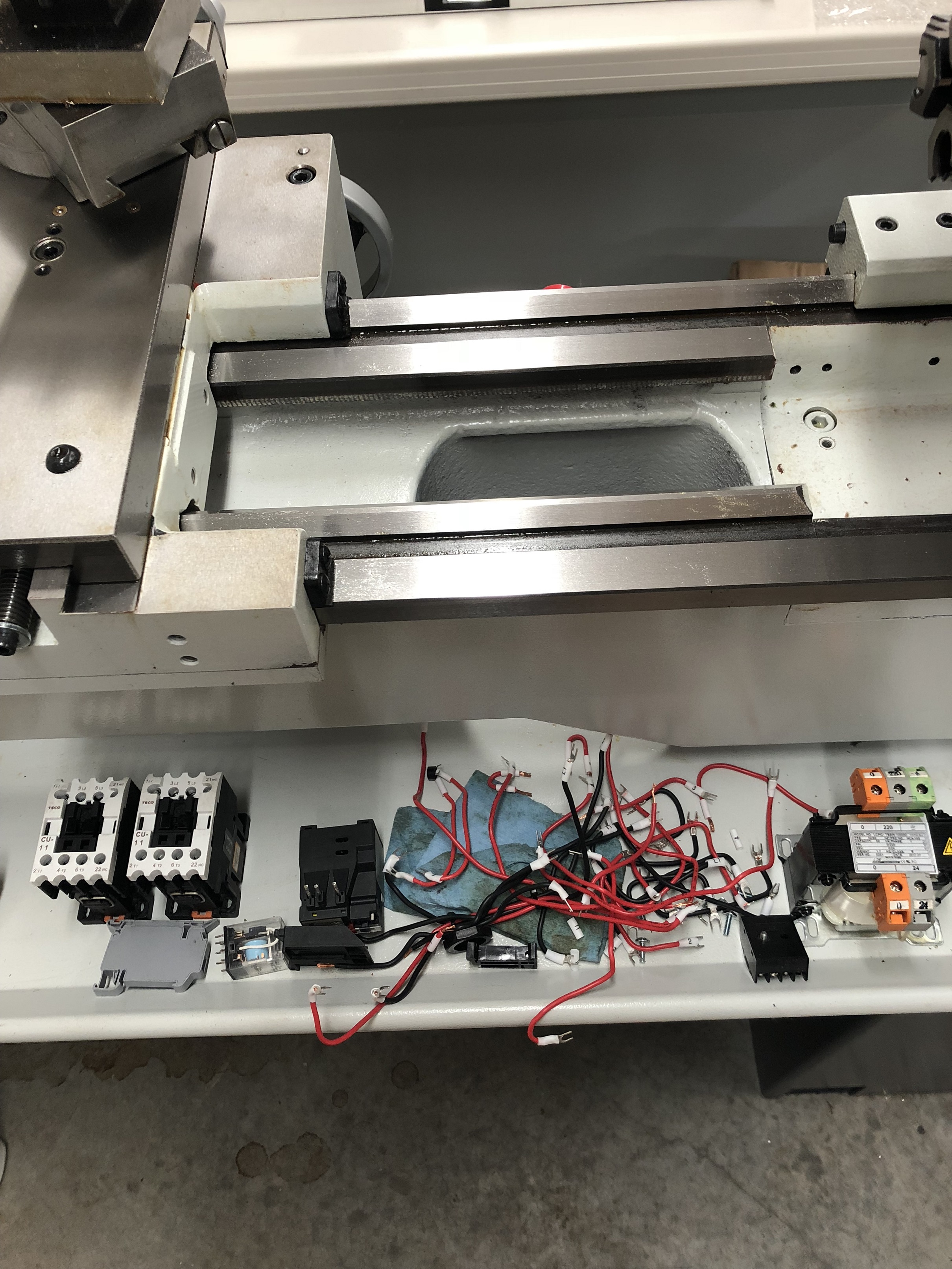
Now onto the install of the scales, this is the part that makes me sweat, drilling into the cross slide and tapping with a 6mm tap, first hole done, I usually drill one hole then align the piece and then mark the other holes with a transfer punch just in case the drill wanders a little, I get to correct for each hole this way.

IMG_2083.JPG


This part finished, now for the scales, I``ll finish those later tonight.

IMG_2085.JPG


I hope the bracket clears the cover as I plan on installing the covers, if not I can always mill out a bit from this bracket to make clearance.

More to come.

David.
 
Last edited:
Back
Top