Next project: Craftsman 101.07301 6" lathe

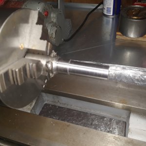
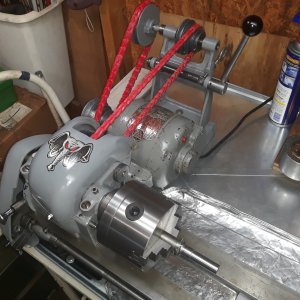
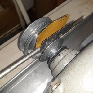
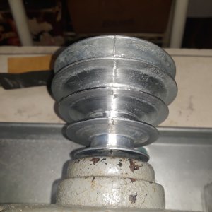
A little more busy work this morning. I was able to reduce the some vibration between the "cast" shieve of the motor with the link belt. Of course that small vibration is transferred thru the motor, to the table and them to the lathe. The casting joints of the shieve were a littIe raised up. I used a steel bar and 100 grit paper to sand the groove sides while the motor was running. Only did one groove as shown.
 

Attachments

  • 20211106_120444.jpg
    20211106_120444.jpg
    3 MB · Views: 14
  • 20211106_120532.jpg
    20211106_120532.jpg
    3 MB · Views: 9
Last edited:
Link belts (any brand) are known to stretch from new. As a general rule, run it a day or three and then removea [ink. Normally, one would probably leave the belt un-tensioned when the lathe is not in use. But after installing a new link belt, leave it tensioned until it stretches enough to remove a link. Or in your case, maybe two.
 
Finally my 3/8" belt came in and got it up and running. While trying to do some final adjustment a "jerry rigged" spacer next to the bull gear and housing failed. The nut on the end of a tiny makeshift band using a machine screw stripped out. "Of course" not having anything that small to make a repair I used safety wire to pull it tight. When I did assembly I just used the band as I didn't have the correct part. I'll have to order from clausing, I hope, the spacer that goes between the bull gear and the housing. I did my first cut and facing and it really came out nice!
 

Attachments

  • 20211106_153743_resized.jpg
    20211106_153743_resized.jpg
    1.5 MB · Views: 9
  • 20211106_160826_resized.jpg
    20211106_160826_resized.jpg
    1.4 MB · Views: 11
  • 20211106_164705_resized.jpg
    20211106_164705_resized.jpg
    1.2 MB · Views: 14
  • 20211106_164307.jpg
    20211106_164307.jpg
    3.3 MB · Views: 12
There are files for 3D printing larger dials on thingiverse free to download. Also Mr. Pete did a video on making them from metal.

Replying to asking about bigger dials above.
 
There are files for 3D printing larger dials on thingiverse free to download. Also Mr. Pete did a video on making them from metal.

Replying to asking about bigger dials above.
If someone has their spindle apart maybe they could give me the dimentions of the spacer and I could lathe one. It I take it apart to get the specs I would have a working lathe to make it. Don't really want to disassemble a nd assemble 4 times. Anyone know if there are specs online?
 
Last edited:
I'm really happy with the outcome of renovation except with "one" darn thing! The infamous problem of the crossfeed backlash. Mine is about .015" and just "loosy goosy" can't live with that! There just has to be a hack short or getting a new screw and brass nut or ball screw assembly. (If they even make one for such a small lathe.) This problem has existed for the longest time and seems someone has come up with something short of replacing the whole lathe! With my lack of experience I would not even attempt to make a new screw. I know some have done that and might be willing to pay a real machinist to make me one if it wasn't cost prohibitive.
 
Last night I let the lathe run for about an hour, in neutral, to help stretch and get some flexibility in the belts. I noticed that the left housing was getting pretty warm and I believe I have the spindle nut too tight. Might have something to do with the spindle nut being too tight and may be another reason I need the spacer next to the bull gear on the spindle.

Update: 11/7/21@ 5pm
The spindle nut was too tight. I loosened it up a tad and ran for about 30 minutes and it wasn't even warm. Gotta check into what the horizontal movement measurement is at the check from proper nut tightening. But then I still need that collar on the right side.
 

Attachments

  • 20211106_160826_resized.jpg
    20211106_160826_resized.jpg
    1.4 MB · Views: 11
Last edited:
Somewhere in this video (around 0:37) it shows how to make a "backlash eliminator" . You make a slot in the brass nut and put in a set screw to spread the slot . You can then adjust out the backlash .
<iframe width="900" height="506" src="
" title="YouTube video player" frameborder="0" allow="accelerometer; autoplay; clipboard-write; encrypted-media; gyroscope; picture-in-picture" allowfullscreen></iframe>
Thanks for sharing that video with me!! It was very informative with ideas on how to overcome backlash.
 
"NOW I FEEL DUMBER THAN DIRT!" Just got back inside the house, from the shop, after removing the "compound slide" and discovered two problems. First all this time I've been saying problem was with the cross slide when I actually meant the compound slide! Second I discovered there is a set screw hidden under the slide that locks the brass nut down. I had not screwed the set screw down cause I didn't see it. Guess what? I only now have .006" slop on the compound slide. The cross slide has .010" and I can live with the backlash in both of these!
 

Attachments

  • 20211107_142624.jpg
    20211107_142624.jpg
    3.1 MB · Views: 7
Last edited:
Back
Top