Old Westinghouse Motor "Rebuild"

bug_hunter

Registered
Registered
Joined
Feb 4, 2021
Messages
171
Hey Guys,

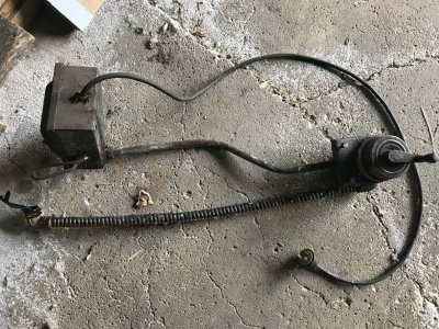
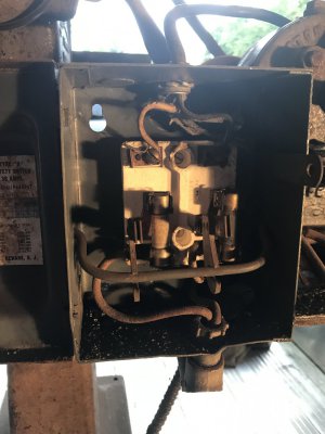
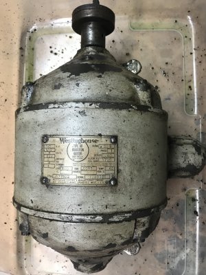
Recently picked up an old Burke No. 4 Horizontal Mill. Does not look like it has run in a LONG time. The motor is an old Westinghouse 1/2hp motor (1 phase 110/220). Photo attached. Just cleaned some of the old dirt and oil off of it, and I would like to see if it will run, and if so, clean it up and put a coat of paint and use it. Can someone out there point me towards a good procedure (written, or youtube) that I could follow to complete this process? I also took a photo of the power system. The two wires on the left side of the electrical assembly entered the motor through the bump-out on the
right side of the motor.

Couple general questions:

- Given that there are oil cups, does that infer that there are no bearings?
- No attached wiring diagram, so how can I tell if it is wired for 110 or 220? (I would prefer 110) Can I assume that since there were only two wires going into the motor, that it is wired for 110?
- Why would the power need to go through the mills own fuse box, instead of directly to the switch, and into the motor? (I've also included a phot of the guts of the fuse box.)

Please share any suggestions, insight, or warnings.

Thanks,

Greg
IMG-1299.jpgIMG-1300.jpg
IMG-1260.jpg
 
The fact that both legs of the fused disconnect are fused suggests to me that it may be wired for 220 volts. The additional wires for the other voltage may be inside the motor, or maybe it could have been rewound sometime in the past for a single voltage. The oil cups mean that it is equipped with sleeve bearings, which work just fine if not excessively worn, to the extent that the rotor rubs on the stator. I'd try starting it on 110V if it is slow starting, it is likely wired for 220V,
 
When you say try starting, would that entail hooking the hot and neutral to the two existing leads, and the ground to the motor case, and plugging it in? I would also think it might be a good idea to put a bit of oil in the cups, just in case it runs. Any particular continuity's that I should check before plugging it in?
 
One reason for the fuse box is the power lever could be padlocked to prevent unauthorized use- an extra layer of safety if you have curious children around
I agree with the other folks, looks like a twist lock plug = 220 volts
We may be able to figure out how to change the motor to 110, you need to open it up and show the inside
-M
 
Last edited:
Sure looks like a 220 v plug to me. Another reason for the fuse box is the circuit it was connected to may have had higher amp breaker/fuses.
 
Per your picture of the motor nameplate the motor can be configured for either 110V or 220V. The motor junction box as you referenced the “bump out” may have the stator wiring configuration for each voltage level on the inside cover. If so, it will be easy to verify the wire configuration / voltage level it was operated with. Then if desired you can wire to 110V if it was setup to operate on 220.

The fuse box or safety disconnect if supplied from the equipment’s manufacturer would have provided the 2 fuses so the motor could be operated with either voltage level. If you can see any fuse value, amp rating, on the fuses that may help identify the last voltage the motor was operated with. The nameplate states 110V is 8 amps and 220V is 4 amps. I would expect you will likely have 15 amp fuses however.

I would suggest updating to new wire from the power supply to the motor terminations no matter what the voltage level is. Understand this is only a ½ H.P motor however it is a good practice to not have a motor unrestrained, just sitting on a bench or floor when starting from a mains power source. That is any time a motor without a slow start feature is started. I have seen a larger motor go rolling across a shop floor due to the sudden high centrifugal force that can be generated at startup. Trust me you don’t ever want to see that.

Good luck with your new project!
 
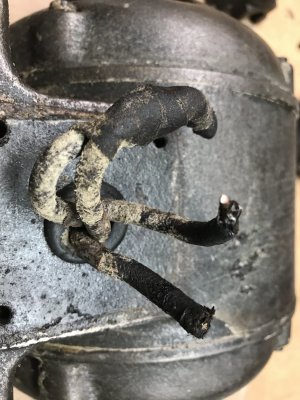
No help in the junction box. Photo below. Just four wires, two that went to the breaker box, and two fastened together. See photo:

IMG-1304.jpg

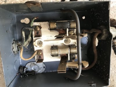
I can't believe the fuse box is original. Appears to be a bit newer than the motor. One of he fuses is 20 amp, the other is illegible. Looks to me that a black and white wire enter the fuse box, each goes to a separate fuse, then onto the motor. There is a ground that enters the fuse box, and is just hanging there. Photo attached. That would lead me to believe that the two wires are hot, and would intern be supplying 220 volts. Logical or not? Does 220 operate without a neutral, like 110 does? Can there be only two hot wires, and nothing else?

IMG-1305.jpg

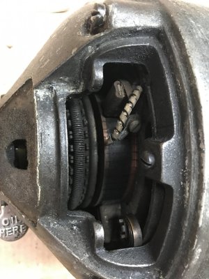
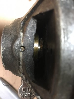
It is my intention to replace all of the wires, just not sure how to get to them. Do I need to take the ends off eh motor and pull it completely apart? There are a couple access ports on the motor that. when removed, may shed some light on things. I snapped a couple photos. It looks like there are brushes, and on the second photo a loosely fitting brass ring. This ring is on both sides of the motor. Any ideas on what tat is for? I cannot see any capacitors on the the motor. Could it operate without a capacitor, or would it be hidden within the case?

IMG-1302.jpgIMG-1303.jpg

The ultimate plan is to be able to run the motor at 110. Any help, questions, or direction would be appreciated.

Thanks!
 
That would be a dual voltage motor, for 110 volts, the two wires that are connected together would be separated and tied to the other two wires, so you would have two pairs of two wires to the 110V supply, there would likely no connections to do anything with inside the motor, and no capacitor, as it looks like a wound rotor with brushes and likely a starting switch inside the rotor somewhere, a repulsion start/induction run setup, this gives high starting torque with low current. Personally I would leave it as is and run it on 220V.
 
No go on leaving at at 220 as I do not currently have that option in my shop. How can I tell which of the two (currently joined) wires should go on which of the currently not joint wires? That did not sound very good, but I think you get the idea.
 
No go on leaving at at 220 as I do not currently have that option in my shop. How can I tell which of the two (currently joined) wires should go on which of the currently not joint wires? That did not sound very good, but I think you get the idea.
Without the wires being numbered, it is a bit of a crapshoot, I remember that motor shops use reduced voltage for test purposes, using an autotransformer to supply the voltage.
 
Back
Top