- Joined
- Jan 2, 2014
- Messages
- 8,852
hey dirty tools,
I am still not sure of what I am looking at.
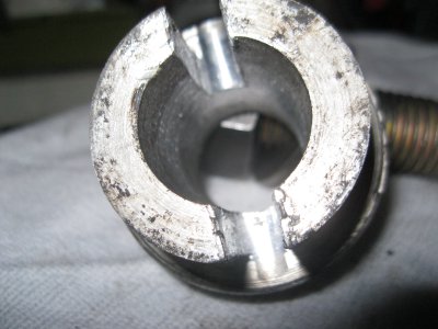
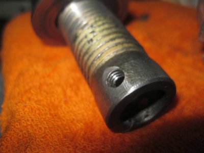
In the picture with the tap, yep that is a tap in the centre of the frame, but we need to see the tube itself. What is it pressed into?
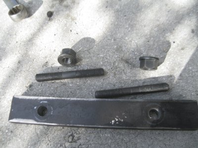
In the other picture I assume that is some puller you created, but I am not sure what parts are the puller, and what is to be pulled!?!!?
Two of the parts seem to have a slot that could be meant for a special wrench, but are those part of your puller or part of the job?
Tell me if I am wrong, but I believe the idea to push it out hydraulicly with grease (suggests by two users above) is a non-starter because:
1) although it is "blind" meaning you cannot get to the backside to simply press the tube out, it is not "sealed" as there are some air channels back there, and
2) even if you could seal it, you would then have your tire inflation pathways full of grease
This is part of a inflate/deflate "on the fly" system. Is that right?
like this:
http://www.lynchhummer.com/componentpages/CTI.html
I am honestly trying to help, I am just not yet sure of the nature of the problem.
Sorry if it's just me being dense.
-brino


