PM-833TV unload and install

AllenV

H-M Supporter - Gold Member
H-M Supporter Gold Member
Joined
Dec 25, 2017
Messages
141
This thread continues from my earlier discussion of which version of PM-833 to buy. That can be found in this link:

https://www.hobby-machinist.com/threads/pros-and-cons-of-geared-head-and-variable-speed.106820/

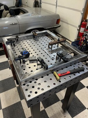
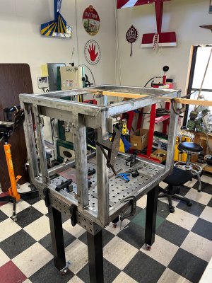
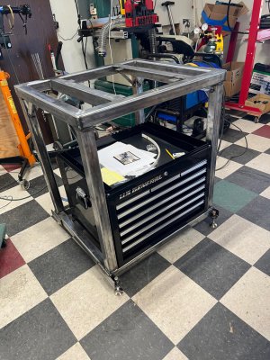
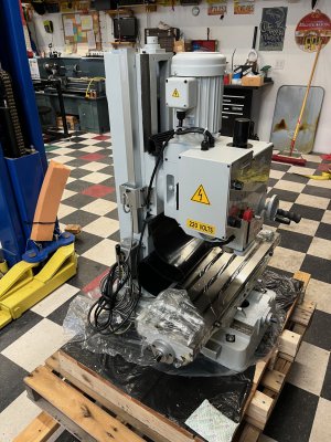
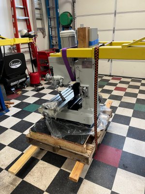
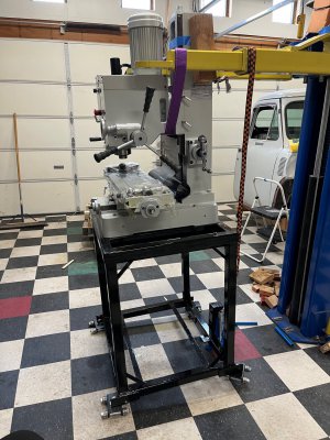
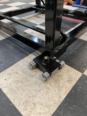
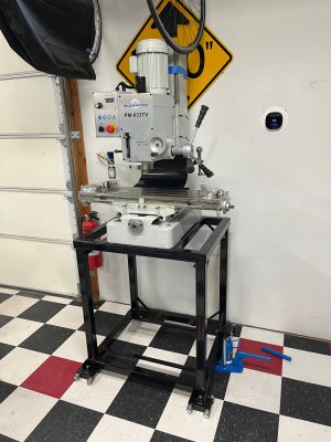
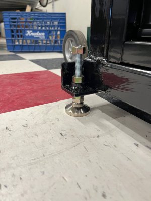
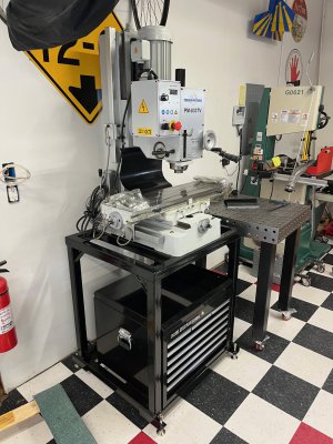
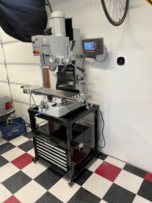
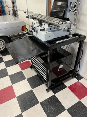
So, with a PM-833TV mill ordered I set about fabricating a stand for it. I wanted something that would hold an HF 26-inch toolbox underneath. Construction is primarily of 3/16” wall thickness 2-inch square steel tube. The supports that sit under the left/right sides of the base casting are 1/4” thick 2-inch angle stock. The design is derivative of several I have seen on this forum. Thank you all for posting your great ideas!

The welding is MIG. My welding skills do not win beauty contests.

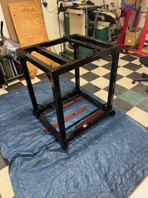
The paint is brushed on
 

Attachments

  • IMG_1703.jpeg
    IMG_1703.jpeg
    357.2 KB · Views: 74
  • IMG_1707.jpeg
    IMG_1707.jpeg
    375.8 KB · Views: 80
  • IMG_1710.jpeg
    IMG_1710.jpeg
    434 KB · Views: 78
  • IMG_1713.jpeg
    IMG_1713.jpeg
    524.9 KB · Views: 81
The mill arrived in town last week. My shop is in the back yard accessed by a dirt drive that is soft in spots, and narrow. It has a track record of getting delivery trucks stuck. I opted to collect the mill at the freight warehouse. The unloading process takes advantage of my 10000 lb. 2-post lift. When I bought the steel for the mill stand I also bought enough to make a stand for my Enco 13x40 lathe. I had already cut and mitered long pieces of ¼” wall 2-inch square tube that perfectly fit under the pallet. These gave me secure lift points fore and aft.
 

Attachments

  • IMG_1715.jpeg
    IMG_1715.jpeg
    603.8 KB · Views: 82
  • IMG_1716.jpeg
    IMG_1716.jpeg
    317.4 KB · Views: 82
  • IMG_1718.jpeg
    IMG_1718.jpeg
    406 KB · Views: 88
  • IMG_1720.jpeg
    IMG_1720.jpeg
    322.1 KB · Views: 87
  • IMG_1726.jpeg
    IMG_1726.jpeg
    410.6 KB · Views: 90
Last edited:
Lifting onto the stand also used the 2-post. Something to note here is that 2-post lifts do not have huge vertical travel. Mine will lift a vehicle slightly less than 6 feet. This is why I rigged the lift arms on each side of the column. The 4x4 blocks are in there to protect the paint as well as the DRO z-axis scale.
 

Attachments

  • IMG_1727.jpeg
    IMG_1727.jpeg
    396.7 KB · Views: 86
  • IMG_1729.jpeg
    IMG_1729.jpeg
    371.5 KB · Views: 82
Last edited:
The mill was then rolled its stand to its final position. The foot brackets were designed around the idea of using machine skates for movement. And then swapping in conventional feet. A Vevor toe jack does a great job of lifting half the stand enough to change skates for feet and aiding in the leveling process.

The skates came from here:

https://www.ebay.com/itm/1138913334...rand=Unbranded&_trksid=p3458402.c101506.m1851

I will use the same skates to move the lathe, when the time comes.
 

Attachments

  • IMG_1731.jpeg
    IMG_1731.jpeg
    408.9 KB · Views: 103
  • IMG_1732.jpeg
    IMG_1732.jpeg
    297 KB · Views: 90
  • IMG_1739.jpeg
    IMG_1739.jpeg
    218.2 KB · Views: 94
  • IMG_1734.jpeg
    IMG_1734.jpeg
    337.3 KB · Views: 92
Here the DRO and the x-axis power feed have been installed. The DRO is the Precision Matthews option item with glass scales.

The stand has a slide-out “chips and drips” tray. This is version 1, fabricated of some left over compressed hardboard sheet ( the stuff they make pegboard out of). If this proves durable, I/m done. If not, version 2.
 

Attachments

  • IMG_1744.jpeg
    IMG_1744.jpeg
    309 KB · Views: 81
  • IMG_1745.jpeg
    IMG_1745.jpeg
    374.1 KB · Views: 74
Today I went out to begin installing the Z-axis power feed, as optioned from PM.

It looks really nice. But I do see a complication regarding the positioning of the z-axis limit switches. According to the PM install instructions, the switches attach to the head and the “stops” attach to the left side of the column using some extruded aluminum track.

The complication is that this is precisely where PM installed the z-axis DRO scale. I am really quite impressed with the quality of the PM DRO installation. It seems to work flawlessly and looks good as well. Thus I am loath to move it.

There is room to put the limit switches in the right side of the column, or I could mount the switch assembly on the DRO bracket with the stop further back. I don’t like mounting the switches on the DRO bracket for fear that the switch activation might distort the DRO and cause some reading errors.

I have great respect for the collective experience of the forum. Thus, before I just start doing something, I am asking you all for suggestions or to let me know how you installed limit switches with your DRO.

See images below. The last one is a screen shot from the PM manual
 

Attachments

  • IMG_1750.jpeg
    IMG_1750.jpeg
    243.7 KB · Views: 53
  • IMG_1751.jpeg
    IMG_1751.jpeg
    273.5 KB · Views: 51
  • Screenshot 2023-09-18 at 1.44.50 PM.png
    Screenshot 2023-09-18 at 1.44.50 PM.png
    898.1 KB · Views: 57
Congrats on the new mill. I am sure you will enjoy it.
I believe there is a thread where a member talked about the same issue of where to locate the DRO scales vs having the Z-axis limit switches.

Utilizing the car lift to move the mill was awesome! I wish I had that option.

EDIT: I found the thread I was thinking of. Not sure how much help it will be but here ya go. https://www.hobby-machinist.com/threads/pm-833tv-z-axis-limit-switch-mounting.106648/page-2
Thanks for the linked thread. It is an example of right-side mounting.

As I mull it over the right side seems the most attractive. I think I can trim the stop extrusions so as not interfere with the name plate. Electrically, I may have to go into the switch and reverse the wires as the switch body gets flipped up for down.
 
Back
Top