PM-833TV unload and install

Nice to get new shop tools!!!! The only thing a bit off to me is that the toolbox is really low to the floor. Maybe you should reconsider and lift it up to just under the pullout tray so you don't have to bend over so low to get into the drawers. Really nice setup good luck.
 
Nice to get new shop tools!!!! The only thing a bit off to me is that the toolbox is really low to the floor. Maybe you should reconsider and lift it up to just under the pullout tray so you don't have to bend over so low to get into the drawers. Really nice setup good luck.
Thank you. Lifting that box might happen. At the moment, though, I am rather liking it low. I use the rolly chair to sit and rummage. An unexpected plus is that the clear space above gives room to open the top hatch. I have stashed a bunch of those fancy tools that come in their own special boxes up there. 'til now those were sitting out making clutter.
 
Everything looks so nice, organized and clean! I will be interested to hear how you feel about the mill (accuracy etc.) once you have used it for a while.

One thing I did notice about your nice stand, tool box, and slide out tray is that you may want to add a drip pan below the mill and above the pull out tray. I find that a lot of oil drips down inside the mill and it would be right on your tray or tool box. This oil, and of course milling debris, makes its way to the floor. My 940M is on the PM base which has a oil catch around the outside of the mill, but nothing directly under it (y-axis lead screw area) and it is hollow in there. So I eventually put in a large cookie sheet pan (has a ~3/4 inch lip on it) to catch the oil and keep it off the floor. Recently I put a drain on the pan with a tube going to a can to collect the oil. My machine has an auto oilier and this keeps the ways and the lead screws wet with oil, which is good, but it uses more oil than one might think was needed.

Have fun.

Dave L>
I am looking forward to using it. I haven't even installed the drawbar yet! As I slowly get the install finished I plan to post initial measurements of column and spindle squareness.

That tray I included is meant to catch swarf as well as all the oil drips. The stand leaves the interior of the base fully exposed to let stuff fall onto the tray. My hope is that that will be enough. Though I like like your thought of adding a cookie tray, just sitting on the sliding tray. I also omitted a "top deck" on the left and right of the base. This is meant to encourage swarf to find the tray and not the floor. Mental concepts abound for swarf catchers to direct material through the open deck. But all of that is a distraction to getting the machine up and running.
 
Do you plan on installing a power draw bar? I took delivery of my 833TV about 3 months ago and haven’t even fully set it up yet. I played around with using the draw bar and a strap wrench and quickly realized that it’s going to be an extreme pain to switch out bits. im trying to figure out the best route to go for this as the priest tools solution is expensive.
 
Do you plan on installing a power draw bar? I took delivery of my 833TV about 3 months ago and haven’t even fully set it up yet. I played around with using the draw bar and a strap wrench and quickly realized that it’s going to be an extreme pain to switch out bits. im trying to figure out the best route to go for this as the priest tools solution is expensive.
No, I don’t intend to use a power draw bar. My 833 came with a spline wrench that fits the exposed spline at the top of the head. The very top of the spindle assembly. Although I have not tried it, I expect the spline wrench will a fine job of holding the spindle while the drawbar is loosened.
my wrench was packed in the little blue toolbox along with the measured data for quality inspection.
 
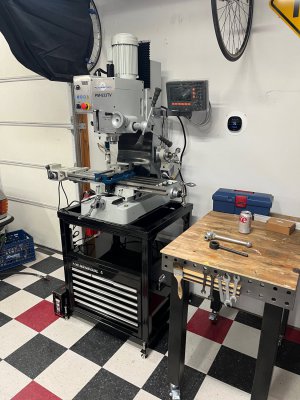
The Z-axis power feed is now installed. This did not go easily. Here I’d like to highlight what I would do differently, and why, if I were to do it again. I will refer directly to the PM-833TV manual section “INSTALLING THE HEADSTOCK POWER FEED”. That document is on PM’s website here:

https://www.precisionmatthews.com/shop/pm-833tv-ultra-precision-milling-machine/

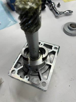
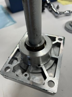
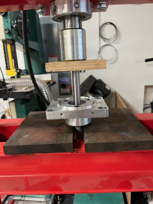
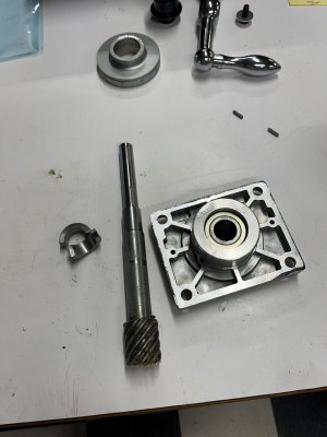
The procedure step 3 says, “Using a soft mallet, tap the gear shaft clear of the main flange.” My unit has a full-on press fit of the shaft into the bearings. Tapping would only serve to damage the bearings. I used the lathe to fabricate a split collar fitting inside the recess of the main flange supporting the inner race of the bearing while in a hydraulic press. The press got the shaft out with a few thousand pounds of pressure and a loud pop every time the shaft moved. (The image below shows a piece of plywood on the end of the shaft. That bit of wishful thinking failed with crushing of the wood. A piece of quarter-inch soft steel plate worked fine.)

Moving on:

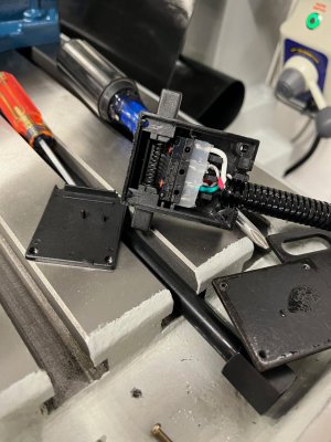
Step 4 instructs to plug the replacement (longer) gear shaft AS FAR AS IT WILL GO into the extender. This is to be done without the main flange. Then step 5 instructs to drill for the pair of roll pins and step 6 “taps” the replacement shaft into the main flange bearings. Steps 7 and 8 install the pins.

After drilling for the first roll pin, nearest the gear, I formulated an improved procedure that did not require inserting the first roll pin, drilling for he second pin, and removing the first pin prior to putting the shaft in the bearing.

With one hole drilled, I pressed the shaft into the bearing flange. I then intended to insert the first pin and drill for the second pin with the flange in place. Then insert the second pin and be done with it. (CAUTION, my drill press vise has the height to let the flange clear the table so I can drill the assembly.)

HOWEVER: When I slipped the extender onto the shaft it would not go on far enough for the drilled holes to line up. I spent far too much time puzzling over this before mounting the extender in the lathe and facing less than 1 mm off of the end. Just enough to allow the holes to line up for pinning.

I was then able to press the first pin in. I then put the assembly in the drill press to drill the second hole. Back to the press to insert the second pin.

The second pin I found to be slightly longer than the diameter of the shaft. I filed the excess away.

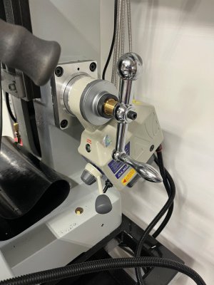
STEP 12: Here we are instructed to use the SAME three M6 screws that held the inner collar to the main flange to now hold the motor mount collar. That is a “no go”. The original screws are much too short. I spent a morning chasing down three M6x25 cap screws. I cut those down to the right length. M6x20 would have worked.

In Summary, if you are doing this.
1) Plan on using a press to get the shaft out of and back in to the bearing flange.
2) If your drill press will allow. Press the new shaft in to the bearing flange. Then drill for the roll pins and insert them.
3) Get some longer screws for the motor mount collar.

My Apologies: The photographic record ceased while I was dealing with the pins.
 

Attachments

  • IMG_1753.jpeg
    IMG_1753.jpeg
    167.2 KB · Views: 34
  • IMG_1754.jpeg
    IMG_1754.jpeg
    178.2 KB · Views: 41
  • IMG_1756.jpeg
    IMG_1756.jpeg
    247.6 KB · Views: 36
  • IMG_1758.jpeg
    IMG_1758.jpeg
    195.2 KB · Views: 36
  • IMG_1766.jpeg
    IMG_1766.jpeg
    234.2 KB · Views: 40
On z-axis limit switches.
I removed the shell from the Align limit switch. It is indeed a simple matter to lift the lift he guts out of the shell, flip it all over, and put it back together. This reverses the top and bottom, up down, orientation operation on the right-hand side of the column. I have done the reversal but have not mounted switches.
 

Attachments

  • IMG_1764.jpeg
    IMG_1764.jpeg
    271.5 KB · Views: 31
More on switches:
Looking at the whole setup I am strongly favoring a heavy rework of the limit switches and doing something along the lines of the solution linked in post #7, above, identified by 7milesup.

Mounting the actual switches on the fixed column and just putting a fixed "finger" on the head puts all the cabling at the back of the machine. Putting the switch and cables on the head looks to interfere with a number of routine mill operations.
 
Here is the beauty shot, as it stands now.
 

Attachments

  • IMG_1769.jpeg
    IMG_1769.jpeg
    333.3 KB · Views: 71
Back
Top