PM-833TV unload and install

I agree, the limit switches as shown in the link at #7 look really nice. My limit switches from the factory were something in a similar location, but the switch is the moving part and the limit bumps are fixed/adjustible. The biggest problem is whether or not this mount leaves room for a DRO mount on that side, unless the DRO is mounted to be farther away from the column.

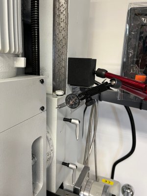
By the way, my 940M also has the Kipp lock style locks for the vertical. I used them early on, but once I had removed my gib for an inspection I never used them again. The lock bolts had made big dig marks in the back side of the gib where the bolt ends touched down on the gib .... and perhaps was part of the reason the gib was bent!? It was a bad install at the China factory where they had cut the gib off too short before fully inserting it. Hence, the gib end screws did not engage properly and so the gib could/would slide about when the vertical direction was reversed. Rather than fix this correctly before shipping it, they just tightened up the Kipp locks until the gib rubbed the ways all the time! Took me a while to figure out what they had done incorrectly and to fix it enough to use the mill.

Dave L.
 
For the tool's first-ever chips I decided to square up a ratty old block of aluminum and then dive in to my first-ever use of a DRO.

I squared the block using a 4-inch vise and a Shars 2-inch insert-style face mill. Running at about 800 RPM and taking 0.050” cuts I got a nice finish with no ridges detectable by my fingers. The photos tell it.

Then I used that same block to make a rib feature as close to 0.750 inches as I could manage. I selected my most rigid cutter. A 5/8 shank many-flute design that has been around for ages. It has clearly been sharpened. I measured it at 0.856” dia. before the mill operation. Then I used it first to create a fresh face as the “back” of the rib. Then I translated the stage on Y, using the DRO, by 0.7500+0.8560 so that cutting the front face would leave a 0.7500 rib. That 4th decimal point is “desired”. My 5 micrometer scales flip that 4th decimal by 2 or 3. The DRO precision is sort of +/- 1 or 2 ten-thousands of an inch.

Each pass cutting got a spring pass. I did not do any intermediate, or final, measurements with the piece still in the vise. It was all on the DRO

My measure final result was 0.7495”. Pretty good. But then I went back and remeasured the cutter. This time the cutter measured 0.8565”. Maybe the warm cutter expanded? Maybe my initial cutter measurement was rubbish? That slightly larger cutter diameter would absolutely make the difference.

All in all, I call this successful. An intermediate width measurement after making the first pass on the front face would certainly have removed the cutter size uncertainty and shaved off a few ten-thousands of error.

Images below
 

Attachments

  • IMG_1786.jpeg
    IMG_1786.jpeg
    333.7 KB · Views: 59
  • IMG_1787.jpeg
    IMG_1787.jpeg
    349 KB · Views: 60
  • IMG_1791.jpeg
    IMG_1791.jpeg
    378.5 KB · Views: 61
  • IMG_1794.jpeg
    IMG_1794.jpeg
    398.9 KB · Views: 64
  • IMG_1797.jpeg
    IMG_1797.jpeg
    218.9 KB · Views: 62
For the tool's first-ever chips I decided to square up a ratty old block of aluminum and then dive in to my first-ever use of a DRO.

I squared the block using a 4-inch vise and a Shars 2-inch insert-style face mill. Running at about 800 RPM and taking 0.050” cuts I got a nice finish with no ridges detectable by my fingers. The photos tell it.

Then I used that same block to make a rib feature as close to 0.750 inches as I could manage. I selected my most rigid cutter. A 5/8 shank many-flute design that has been around for ages. It has clearly been sharpened. I measured it at 0.856” dia. before the mill operation. Then I used it first to create a fresh face as the “back” of the rib. Then I translated the stage on Y, using the DRO, by 0.7500+0.8560 so that cutting the front face would leave a 0.7500 rib. That 4th decimal point is “desired”. My 5 micrometer scales flip that 4th decimal by 2 or 3. The DRO precision is sort of +/- 1 or 2 ten-thousands of an inch.

Each pass cutting got a spring pass. I did not do any intermediate, or final, measurements with the piece still in the vise. It was all on the DRO

My measure final result was 0.7495”. Pretty good. But then I went back and remeasured the cutter. This time the cutter measured 0.8565”. Maybe the warm cutter expanded? Maybe my initial cutter measurement was rubbish? That slightly larger cutter diameter would absolutely make the difference.

All in all, I call this successful. An intermediate width measurement after making the first pass on the front face would certainly have removed the cutter size uncertainty and shaved off a few ten-thousands of error.

Images below
Very nice results for first cuts. I got my 833TV a few months ago and am in what I think is a similar situation as you - everything I try on it is a 1st time. 1st time on a mill of any kind, 1st time with a DRO, etc. So far I am very happy with the machine and what it can do. The operator, well - lots of room for learning.

BTW, the Z axis limit switches noted above were my project and I'm still happy with the result. On my long list of projects is a similar conversion for the X axis limit switches. The X switch assembly is right in the way of my vise handle etc and the dangling wires bug me. If you would like any more info on what I did for the Z switches let me know - I'm happy to offer any assistance I can.

cheers

Andrew
 
Hey @Andrew_G , thanks for the note. I am really liking the machine. A big improvement over the previous round column RF-40 clone. That DRO introduces a whole new scheme of keeping track of coordinates. Maybe it will wake up some brain cells.

I do like your switch solution. But, right now, the z-switch is just dangling at the back of the column. It may stay there a while. Agreed that the x-switch cable is something of a bother. A simple cable clamp at the left edge of the saddle would go a long way towards keeping that cable out-of-mind.
 
I took another stab at hitting the numbers with a different cutter in steel

But first, I'll mention that I have observed the Z DRO reading shifts by several ten-thousands , or more, when the Z-axis locks are tightened. This may be a gib adjustment issue wherein the head "nod" is changing when the locks essentially tighten the gibs. The DRO head sits a few inches behind the dovetail, so an angle change will reflect in the reading.

Now, I did an exercise to get a precise dimension in steel. This is different than the method used above in Al.
Used an HSS 4-flute, 7/16 diameter cutter
milled a section of 3/16 thick square steel tubing (leftover from making the stand.)
Ran at 550 RPM using Relion cutting fluid
put a fresh face on the back
came to the front and put a fresh face there as well
zero'd the DRO y-axis
measured the width at that point with a micrometer
three measurements, 0.8148, 0.8150, 0.8147 inches
decided to target 0.8000 inches
removed 0.0148 inches in 2 passes as indicated by the DRO

Getting the desired DRO value in the 4th decimal place requires some patience.

Final size, measured three times
0.7999, 0.7997, 0.7997
 

Attachments

  • IMG_1804.jpeg
    IMG_1804.jpeg
    288 KB · Views: 35
In my previous post I mentioned that the Z DRO indicates movement when the Z gib locks are tightened and loosened. I set about measuring the movement of the head on the dovetails. Then I will ask you how much movement is appropriate.

Referring to the 3 attached images. I put an indicator between the column and the base of the head. Then set some wood blocks on the table such that moving the quill downward lifts the head. This resulted in a measured movement of the head on the dovetail of 0.0031" - 0.0032"

I think this is excessive. I am inclined to to tighten the gib to get 0.001" - 0.0015" movement. Is that a good target number for this particular dovetail? I get this value from David Best's @davidpbest posted PM935 table adjustment. He puts his knee tighter than that, but this head dovetail is shorter and the heads hangs in a cantilever fashion so maybe 0.001 or a bit more is appropriate.


Attachments

  • IMG_1809.jpeg
    IMG_1809.jpeg
    336.3 KB · Views: 41
  • IMG_1811.jpeg
    IMG_1811.jpeg
    254.7 KB · Views: 41
  • IMG_1812.mov
    11.6 MB
I now have that Z-axis gib play tightened down to 0.0016"
 
I now have that Z-axis gib play tightened down to 0.0016"
Allen, very informative. I've tried to replicate the measurements you've done on my 833TV. I measure just shy of 0.001" horizontal movement on the head (at approximately the same indicator location as your pic shows) when I lift the head using the quill on a block of wood. That is the movement I see before I lift the head on the backlash in the z leadscrew. So, based on that I'm feeling pretty good. However, more questions come up -

1/ I tried to adjust the z gib and ran the gib to either extreme without being able to lock the z up. My assumption was that at some point I could tighten the gib so much that z movement would become very difficult. The extremes I adjusted to were the point where the gib adjustment screws came out. It looks to me that the 'fat' end of the gib is the upper end, in which case pushing the gib down should tighten things up - is that the case? Were you able to tighten the gib enough to lock the head? I think I will email tech support on Monday.

2/ I see noticeable backlash in the z axis lead screw. After tipping the head as above, I can push harder and lift the head with the quill on a block method as above, as measured by the z axis DRO. Is that similar to what you see/ expect to see?

cheers

Andrew
Andrew, I made no attempt to lock the head in place with the gib adjustment. And, yes, pushing the gib downwards tightened it up.
Now, quite a lot of gib movement downwards was needed to remove that 1-and-a-half thousands of play that I took out. Seemed like maybe 1 cm. Thus I am not surprised by your experience.

One suggestion. Since you are moving the gib. Run it upwards until you get ~0.002" play with upper and lower screws snug. Then run the head up and down to a bit to ensure that all is seated well. Remeasure. Now loosen the bottom screw about 1 turn and snug the top screw. Move the head up and down again and remeasure the play. Iterate this process to get back to your 0.001" play. Tighten the top screw and re-check the play. I think that by doing it this way you will achieve a stable adjustment that won't jiggle loose or tight as you use the machine.

As you e-mail tech support, ask them what amount of play is recommended. The manual is annoyingly vague and non-quantitative on the topic.

FYI, I later measured the table X-axis vertical play. This time by pulling up on the table as hard as I can. I got just about 0.001" total movement. I left it that way.

Finally, I have not explored Z backlash. Seems to me it would be similar to the X or Y screws or a lathe cross-slide. perhaps 0.008-0.015"
The difference being that the head will fall down by gravity and so always load the screw from the top. To measure backlash one might need to lock the head in place and then measure slop in the crank using its markings. Having said all that, I am not certain that Z has adjustable backlash.
Ok, thanks for that. The 0.001" z tip measurement I have is with the gib at the lowest (tightest) end of its travel. I will try loosening and then adjusting back to a similar movement as you suggest. If nothing else it will be informative.

I'll check the x and y play as well and see what i find.

I assumed that there was no adjustment for z backlash, but then started to question how much was reasonable. It is reassuring to hear someone else agree. As I mentioned in a previous post, this is all new to me so I don't have what I'd call 'common' sense wrt machining - that adds to the challenge and fun.

I'll post what I find.

Thanks

Andrew
 
Back
Top