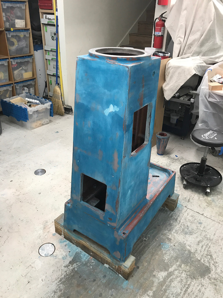
Initial inspection of gibs wasnt too bad. Theres some paint that did make it on to the end of one and the backside. Not optimistic that alone will get me where i want.
Are the tapered seats for the adjustment screws ok? The one in first picture is hardly there and the 2nd looks pretty beat up. Not sure it can do its job properly with the gibs tightened unevenly.
Hi @
nighthawkFmobil
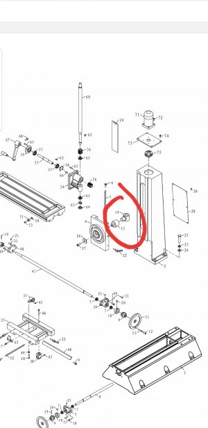
WRT to the gib. The big end, (top), of your gib looks typical. The small end (bottom), of the gib which is chewed off is similar to mine, but not as bad. As I said mine did not work at all as the screw pushes it into the way making it a clamping force, not a gib. I made a washer with a finger sticking out to catch the gib end. At the time I was cutting some thin aluminum and it was clamped to my backer board anyway so I just used this Al. It was thin, so I may have used to layers in the gib hole. I cannot recall. However, something harder would work better.
Just for you..... I have a bridge... for sale...
I will attach two files for you that may be useful. One is just a drawing of the washer. The other has Gcode. In addition I will through in another gcode which you can simulate if you want.... it for the instrument panel I was making. I made 4 washers at the time out of this thin Al. The made the tab a bit large as I figured I was going to have to file by hand to get it to fit anyway. So the ID was to fit the bolt and the OD was to fit the hole where the gib screw head was receding into. That hole on the 940 was not well defined (sloppy) so I made it as large as I could and have it still fit. The finger on it sticks out and I just tried to make it larger than needed so I could file it down. I was actually cutting a much more complex panel plate with lots of odd shaped holes and just put the gib washer on the end of the Al that I was cutting. I put a holding tab on the circle edge so that the part would not tear out as it was being cut.
I will stick the Gcode I wrote for the process, but it is way overly complex and may not make a lot of sense to you.... as I said I was cutting other parts at the same time. I was using a 2mm diameter end mill. Anyway, I was taking very small cuts so the thin parts would not get bent as they came loose or curled out of the cut material. I will also attach my Mach3 Gcode text files for these cuts and another for the washers..... which you can simulate to see what it looks like. This gcode looks extremely complex, but maybe you can extract something that you might want to run. The reason for the complexity is that I actually did the parts design in Visio, then wrote a program in Excell that allowed me to shift and rotate any individual part to a location in the X-Y plane and places its holding tabs at any angle. The Excel program automatically generated the Gcode, which I then made into a text file. Some of the parts also had flats on the circles as well as the holding tabs.... so the Excell was used to calculate where the cutter went from making a circle to making a straight line or where the tool was lifted to make the holding tab... as a function of how the part was shifted in X-Y or rotated. Anyway, I will share it, along with the Gcode for the washers. Maybe you can run the washer Gcode just as it is written, but you may have to make a leap of faith!!!
Not to be incomplete, I will also attach a 4th file, which should be the same as the 12Circles-2Rects.... file but with comments. When I had put all these comments in the file it would not simulate in the MillWizard software as it had too many characters! I cannot recall if it would actually run in Mach3. The MillWizard simulator is actually a lot different from the actual Mach3 software.
Dave