Pm 940v

Initial messaging with pm states this is normal behaviour for a mill to unpredictably nod in
the Y and shift or tilt in the X along the z axis. Ill have to look more into this but it seems odd a 5k$ mill cant consistently sit within at least .003 of perpendicularity to the table.

For now ill just have to keep cleaning it up and checking it out. Hopefully it gets better.
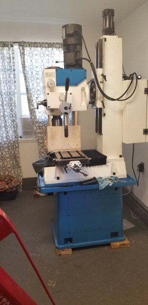
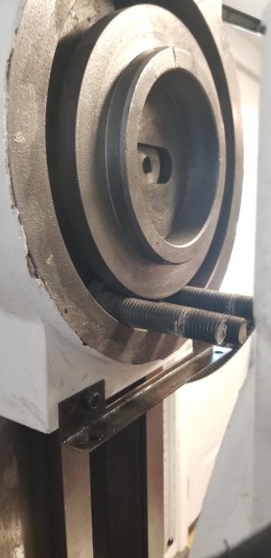
I agree with you about the nodding etc. Others have much better results. If your gib actually fits and you tighten it us really well the slop in the motion will decrease, at least in the y direction. I did this just to test it out. However, if you do this in the center of the vertical then don't try to move the head up and down too far as the ways will get really tight as you approach the top and bottom. I was fearful that I might actually crack the saddle if it got too tight and then cranked the head up high. It will be tighter at the top and the bottom z- axis range of motion because the ways do not bend (as much?) there.

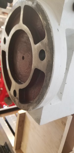
If you really want to know if the lead screw has to come out, you might contact @ptrotter , or just look at his posts, as he took the lead screw out and replaced his lead screws as he rebuilt the machine into a CNC. He took on the task of stripping all the whole surface of the machine and repainting it too! This meant that he basically took it all apart including removing the vertical column. https://www.hobby-machinist.com/threads/new-pm-940v.87161/page-5#post-827110
 
it would be cool to disassemble and bead blast one of these to see what the castings really look like. and do a real paint job.
 
Thanks david, it was a cool tool so i thought id give it a try. Seems to work great.
 

Attachments

  • 20210915_125153.jpg
    20210915_125153.jpg
    923.7 KB · Views: 90
Initial inspection of gibs wasnt too bad. Theres some paint that did make it on to the end of one and the backside. Not optimistic that alone will get me where i want.

Are the tapered seats for the adjustment screws ok? The one in first picture is hardly there and the 2nd looks pretty beat up. Not sure it can do its job properly with the gibs tightened unevenly.
 

Attachments

  • 20210915_125043.jpg
    20210915_125043.jpg
    711.2 KB · Views: 99
  • 20210915_125031.jpg
    20210915_125031.jpg
    804.7 KB · Views: 87
  • 20210915_125001.jpg
    20210915_125001.jpg
    802.2 KB · Views: 89
  • 20210915_124955.jpg
    20210915_124955.jpg
    714.6 KB · Views: 87
  • 20210915_124949.jpg
    20210915_124949.jpg
    1,011 KB · Views: 91
  • 20210915_124934.jpg
    20210915_124934.jpg
    721.1 KB · Views: 79
The head mounting surface has a bunch of paint or some kind of crud. The z carriage has at least paint and some other crud on the flat part that rides the ways. Ill have to figure out how to get the z base plate off.
 

Attachments

  • 20210915_132944.jpg
    20210915_132944.jpg
    668.4 KB · Views: 86
  • 20210915_132955.jpg
    20210915_132955.jpg
    814.5 KB · Views: 78
  • 20210915_133007.jpg
    20210915_133007.jpg
    794.3 KB · Views: 71
  • 20210915_133011.jpg
    20210915_133011.jpg
    812.7 KB · Views: 93
That second gib does not look like it has a good enough surface for the adjusting screw to apply force in the direction needed to slide the gib vertically, and instead looks like the force would be pushing just the end of the gib diagonally into the dovetail. Am I seeing this correctly?
 
That second gib does not look like it has a good enough surface for the adjusting screw to apply force in the direction needed to slide the gib vertically, and instead looks like the force would be pushing just the end of the gib diagonally into the dovetail. Am I seeing this correctly?
Yeah it doesnt seem useful. Its totally different from the other one. Im not sure i can take the carriage off without removing lead screw but it really needs to come off because i can see paint and crud.
 
have you taken that giant electrical box off to look inside the back of the column?
 
pretty sure. you wanted to remove the crank mechanism anyway. and check the lower bearings are not coming loose. in for a penny, in for a pound?

but

there have to be guys who converted one of these to CNC and changed to ballscrews who could tell you exactly what to do to get the leadscrew out.
 
Back
Top