Hi
@nighthawkFmobil
Yes, I have used Excel several times. I use it to do the calculations and then organize things. I usually use variables when I do and one of the problems with the Mach3 is that the available variables are not well defined. It is a bit of a guessing game. Most all of the 9000's, a large fraction of the 8000s, and 7000s are available. You can see what I used in the gcode. You can put the line numbers, GCommands X, Y, Z etc in the columns and then a row becomes a line of G code. Each column has meaning and then in another column you grab each of the cells that you want in the final line and use the CONCATENATE command to gather the cell entries, add spaces, commas, ), etc.
Example: CONCATENATE(B178,C178," ",D178," ",E178," ",F178," ",G178," ",H178," ",I178," ", J178," ",K178," ",L178," ",M178," ",N178," ",O178," [",P178,"] (",Q178,")")
The cell entries can be numbers, text, etc. What ever makes sense in G-code. However, in Excel the numbers will carry too many digits etc for Gcode so you need to make those entries the right number format by limiting the number of digits with a command like rounding.
Example: =+ROUND(E77,4) .
If you decide you want to try your hand at something like this I suggest you start with a simple object.
In the example code that I posted, I took one page to make an object shape. Based upon another page which carries the info for the particular object: shape, size, X-Y location, tab locations on the object, number of tabs, tab widths, flats on a circle, rotation angle etc would feed into the particular page where the characteristics were used to manipulated the values math wise. This way one set ups multiple pages to handle multiple objects. this page generates the G-code text for that particular object.
Then I use a macro system to gather up the various G-codes for each object into a set of G-codes. In this page subroutines are used to call each object to be cut via the main program.
All of this seems rather complex and is, but once written one can create sets of objects with different parameters, location, size, etc. pretty fast and can easily change these if you want a different layout. So on the Gcode I posted for you you can quickly see the set of routines for each of the objects being cut out. But only the final results are in the posting. If you really want to dig deep I could send you an Excel program... but it may take longer to figure it out than to write one for your self.
Obviously, if you are only doing one object this might be a lot easier to just draw it in a CAD package that automatically generates Gcode. Of course if you want to change one object this is not too hard if you only have one object, but if you have a lot it gets to be a little more tedious.
Dave


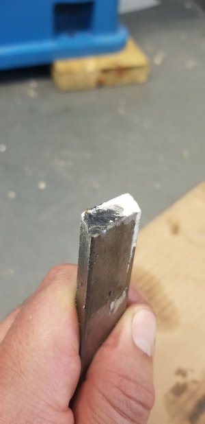
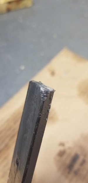
") . Do the jib adjusting screws line up properly in the gib dimples? Is one off center? I was thinking the gib adjustment screws would have a jamb nut so lloctite was not necessary. You may consider swapping out those screws for a better set screw from McMaster? Would rounding the tip slightly help it read in the gib better, and apply a more uniform force?
. Do the jib adjusting screws line up properly in the gib dimples? Is one off center? I was thinking the gib adjustment screws would have a jamb nut so lloctite was not necessary. You may consider swapping out those screws for a better set screw from McMaster? Would rounding the tip slightly help it read in the gib better, and apply a more uniform force?