PM1236 gears

I got it. I will have to look a bit to figure out what you actually have for a gear box.

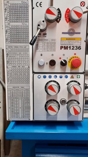
The manual does not provide much in the way of the TPI table. I think it would be really helpful if you were to post some well focused pictures of the front of your lathe, showing the gear knobs etc., but mostly the TPI, Metric, and feed rate tables. The PM photos do not focus on these so I cannot read them and the manual does not provide photos of these.

The only figures I could fine in the manual regarding TPI were the ones at page 19. Figure 1-20 and 1-21 are redundant as they change due to the external gears. Meanwhile in figure 1-20 the MI and MII differ by only the factor of 2 of a single gear so it really only supplies one line of useful information. The line that reads Gearbox A2 A3 C3 A4 C3 C3 C3 A5 B4. From this we only have the gear knob positions a hand full of possibilities. We need more to decipher things.

Dave L.
 
Hi @verbotenwhisky

I was able to decipher a bit more by using the metric table in the manual. Hopefully your pictures will shed more light. So far I have the following ratios for the gear knob settings shown below. MI and MII are simply a factor of 2 so we ignore them for now. Hopefully your tables printed on the lathe will fill in the following table's missing entries. Each knob seems to have 5 possible locations to form 25 possible gear ratios. Unfortunately, this does not look like the 1440GT gear box which only has 4 by 4 lever positions. (The "I" position does not count as it disengages the lead screw. It is for feeding only.) Just as the MI and MII gives a factor of two, in the 1440GT there is a pair of knobs that gives two factors of two, ie 4 multiples.

So we need to fill in the missing values, "?", in the following gear ratio table. In fact, we can fill it in completely if you can find a table with a value for knob# 1 position and at the same table, where the lettered knob is constant, and any of the other numbered knobs positions so that we have a all the ratios between the numbered knobs. For example find a two values for example A1 and A2-3-4-or -5, or C1 and C2-3-4or-5, etc

1674692249085.png

Also, according to the manual you should have the following external gears:
48
24
44
52
38
22
26
127/120
Is this correct?


Dave L.
 
Last edited:
Hi @verbotenwhisky

I was able to decipher a bit more by using the metric table in the manual. Hopefully your pictures will shed more light. So far I have the following ratios for the gear knob settings shown below. MI and MII are simply a factor of 2 so we ignore them for now. Hopefully your tables printed on the lathe will fill in the following table's missing entries. Each knob seems to have 5 possible locations to form 25 possible gear ratios. Unfortunately, this does not look like the 1440GT gear box which only has 4 by 4 lever positions. (The "I" position does not count as it disengages the lead screw. It is for feeding only.) Just as the MI and MII gives a factor of two, in the 1440GT there is a pair of knobs that gives two factors of two, ie 4 multiples.

So we need to fill in the missing values, "?", in the following gear ratio table. In fact, we can fill it in completely if you can find a table with a value for knob# 1 position and at the same table, where the lettered knob is constant, and any of the other numbered knobs positions so that we have a all the ratios between the numbered knobs. For example find a two values for example A1 and A2-3-4-or -5, or C1 and C2-3-4or-5, etc

View attachment 434969
Also, according to the manual you should have the following external gears:
48
24
44
52
38
22
26
127/120
Is this correct?


Dave L.
I am traveling for the next day or 2, I will take the pix and post when I get back to the house, I appreciate the help.
 
Thanks for the info.
I have all the common inch information in the diagram on the main gear box. PM1440HD, Letters and # related to the controls nicely presented. On the main gear box there are concentric levers for driving the lowered gear box. One for reversing rotation and one that doubles/halves.
The lower gear box has a knob for engaging the drive for it. Then a knob labeled 1 thru 8 related to the columns on the upper table. The next knob has 5 positions with center off (disconnect feed & threading shafts.) Of the remaining 4 positions two serve the feed shaft and two the threading shaft. All they do is double or halve. Threading shaft is 8TPI. For imperial threads the only time I have to use different change gears is for the most extreme thread available as standard, 4TPI. All others up to 112TPI are just lever or knob changes. On the banjo only the 127 tooth idler gear is used. For all setting except the 4 TPI the 127 tooth gear only serves an idler. Top & bottom gears running on it are both 40 tooth. For 4 tpi output is halved by using 25 & 50 tooth gears against the 127 tooth idler instead of the two 40 tooth gears.

All metric threads use the 127 idler which is solidly connected to the 120 tooth idler to make the 25.4 metric conversion factor. Two more change gears were include 30 & 32 tooth. Each time one is run against the 127 idler and the other against the 120 tooth. All the metric threads I have ever wanted except two have been available with these gears. Those two missing threads can be had +- close enough by the available gears.

I've considered making change gears to more closely get the missing two threads but haven't figured out what the change gears would be. I made a try but the ratios kept coming up with gear tooth counts to large for the space. I have a set of 8 gear cutters for Module 1.25, 20° I made one duplicate gear for a test run on the lathe and it seems to run fine.

I'm guessing that the feed rates given are close enough for practicality since they are given to 4 places on the chart. I do know that there are a few Japanese standard threads that are not ISO. True all so of old Whitworth. I've never needed to make ISO compatible ACME or Buttress so don't know about those either. Took me awhile to get used to using the change gears. It is also a rathe greasy procedure. I modified the access door to the change gears to make access quicker.
 
@Larry$

The above discussion with @verbotenwhisky is with regard to the PM1236 (not the PM1236T), so he does not have a spread sheet to list all of the TPI values available. Hence, we are working toward solving that.

Sounds like you are pretty well set and know what you have and need. I didnot find much info for the PM1440HD on the PM website. It looks like has PM stopped carrying this lathe and removed the description, manual, most pictures etc. So I have no info on your lathe. I have a PM144GT and it sounds like the gear boxes are similar, but not the same. The 1440GT does not have as many lever positions as your lathe. Perhaps you can post your lathe manual and pictures of the gear tables that are on the front of the machine so that I could understand better.

I built an Excel Workbook that has spread sheets for a few lathe built in. However it is constructed in such a manor to be reasonably easily modified for most other lathe gear boxes and external gears. It might be of use to you so that you do not have to make gears in the future. I find with my PM1440GT spread sheet that almost any TPI can be found and those that cannot be found exactly can be found to a very good approximation. I suspect that with all of the levers and knob positions that you seem to have available you probably never need to use an external gear... or at least seldom. My Excel Workbook can be found at:
TPI Feeds X-Feeds: Generalized Excel file for your Lathe
If you want to try it I suggest you download the zipped file version "TPI Many Lathes M421_1443.zip" . You can at least see how it works. You may need to enable macros on your version of Excel to see the full features of this workbook.
 
Hi @verbotenwhisky

I was able to decipher a bit more by using the metric table in the manual. Hopefully your pictures will shed more light. So far I have the following ratios for the gear knob settings shown below. MI and MII are simply a factor of 2 so we ignore them for now. Hopefully your tables printed on the lathe will fill in the following table's missing entries. Each knob seems to have 5 possible locations to form 25 possible gear ratios. Unfortunately, this does not look like the 1440GT gear box which only has 4 by 4 lever positions. (The "I" position does not count as it disengages the lead screw. It is for feeding only.) Just as the MI and MII gives a factor of two, in the 1440GT there is a pair of knobs that gives two factors of two, ie 4 multiples.

So we need to fill in the missing values, "?", in the following gear ratio table. In fact, we can fill it in completely if you can find a table with a value for knob# 1 position and at the same table, where the lettered knob is constant, and any of the other numbered knobs positions so that we have a all the ratios between the numbered knobs. For example find a two values for example A1 and A2-3-4-or -5, or C1 and C2-3-4or-5, etc

View attachment 434969
Also, according to the manual you should have the following external gears:
48
24
44
52
38
22
26
127/120
Is this correct?


Dave L.
100% correct on the gears, spot on. Let me see if I can attach this picture. See if this is readable.
 

Attachments

  • 20230129_230621.jpg
    20230129_230621.jpg
    264.4 KB · Views: 69
Let me see if I can attach this picture. See if this is readable.
Thanks. Unfortunately, other than the bottom table, "Indicator Table" (Threading Dial), there is no more info on the front of the lathe than there is in the PM manual. I do not think this table helps us to understand the threading (gearing) any more completely than the other tables.

So between the TPI and MM/thread tables I can get gear ratios for each of the gear knob positions (1-5) and (A-E) everything except when the gear knob is set to the position #1. You have to wonder why it is included if they tell you nothing about it and do not tell you what it is used for other than the feed position E1!

I have made a guess at the "1" position gear ratio from the feed tables, but I do not like working with the feed table data as the data provide is never very accurate. All one has to do is take ratios of each the Feed/x-Feed rates given in the tables and you can see the inaccuracy. The ratios should be a constant as all the external and gear box gears cancel out leaving only the gears in the saddle gear box. (However, we know that a single gear will have an integer number of teeth!) I will share these calculations with you after I work them out if you want. My guess is that if you set the upper external gear to 48T, the bottom external gear to 24T, with a common center gear (120T or 127T) in contact with both of these, and then you set the gear knobs to A,1, I and M, you will get 12TPI. You might try scratching a rod over a few inches and see if this is close, or if you have a DRO turn the spindle by hand and count the turns to travel a few inches and then divide the numbers to see if you get 12TPI. This can be a bit tricky to get accuracy so a long scratch thread is almost better... especially if the TPI turns out to be an integer like 12. According to the table the lathe already has a knob position to generate 12TPI, C-3-I-M. You could also make a long scratch thread with both A-1-I-M and C-3-I-M and compare them!

Meanwhile, the manual says: "The S-M knob at right determines which is the driven shaft, leadscrew (M) or carriage feed (S)." "Driven" is the key word here. There is the 8TPI lead screw rod (LS) and then there is the carriage feed rod which simply has the single slot in it. Which of these turns when the knob is in the M position and which turns when in the S position. Do they both turn in either position?

Lastly, I will admit that I have not had much energy for studying the parts diagrams, which are commonly, geometrically, incorrectly laid out or not all of the gear tooth values are provided. Hence, I have not been successful at obtaing exact gear ratios for the Feed or X-Feeds. Hence, I am trying to just try to get an approximate number from tables. I will focus on the metric feed tables as they have more digits in the numbers.

Dave L.
 
Last edited:
Hi @verbotenwhisky

I am attaching the excel TPI workbook that I fixed up to include your PM1236 Lathe (Not the PM1236T which is the same as the PM1340GT that is already one of the sheets in the workbook. In fact, I left the tab pages in place for the other lathes that are included.). So now you should be able to see all of the possible threads that you can cut without or out changing the change gears. Be aware that it is only a draft workbook as all of the gear settings for position "1" of the numbered knob are uncertain as I had to guessed the value based upon the published feed rate (which are not very accurate) for gear position E1. But hopefully after you do the scratch test that I suggested earlier maybe our confidence will improve. Also, I had to estimate the Feed and the X-Feed saddle gear ratios by studying the feed tables in the photo you posted. Because the rates in the tables are inconsistent and typically only have 2 or 3 digits I was again forced to make an estimate for these gear ratios. (I did spend time looking at the exploded parts drawing, but could draw no conclusions from it..... Maybe you want to make a try, but I warn you it is a time sink and I have found these drawings on other lathes to be incorrect or missing information.

Anyway, give it a look and see if you think it is generating the correct numbers. Your lathe tab sheet is called uwPM1236-draft. The uwReadme tab will provide you with information on how to use the sheets and the workbooks as well as explain the "uw" that starts the tab names. Without tese letters when you run some of the macros a house keeping effort deletes the tabs with out the beginning "uw" in the tab name. If you are not familiar with using macros let me know and I will give you a few words about how to get started or just search the internet a bit. (I think I may have also put some of this in the uwReadme tab. ) If you have never used macros in your Excel program you may have to enable them. google the phrase "enabling macros in excel". I wrote this workbook in Office 2010 so it should work on almost any Office Excel program. When you open the file in Excel it will tell you that there are macros and that they can be hazardous so it will ask you to confirm that you want to enable them. If you do not enable them you cannot run the macros, but you can still use the spread sheet for your lathe to find TPI values "one at a time". Anyway, I wrote the macros myself and other HM have been running them. The Macros are very handy.

Lastly, I ran the TPI generator for you and the results of that are shown in the tab called AllTPI (the first tab) as well as in the one that will not get erased by running the TPI generator, "uwAllTPI-PM1236-draft".

The file name after unzipping is "TPI Many Lathes add PM1236-draft N130_2317.xlsm". The N130_2317 is my short hand code for a date stamp. N=2023, 1=Jan., 30= the day of the month, followed by Military 24 hour time stamp, 2317 = 11:17PM. I do this to keep track of the version of the file I am working with.

Fingers Crossed.

Dave L.
 

Attachments

  • TPI Many Lathes add PM1236-draft N130_2333.zip
    1.3 MB · Views: 39
Thanks. Unfortunately, other than the bottom table, "Indicator Table" (Threading Dial), there is no more info on the front of the lathe than there is in the PM manual. I do not think this table helps us to understand the threading (gearing) any more completely than the other tables.

So between the TPI and MM/thread tables I can get gear ratios for each of the gear knob positions (1-5) and (A-E) everything except when the gear knob is set to the position #1. You have to wonder why it is included if they tell you nothing about it and do not tell you what it is used for other than the feed position E1!

I have made a guess at the "1" position gear ratio from the feed tables, but I do not like working with the feed table data as the data provide is never very accurate. All one has to do is take ratios of each the Feed/x-Feed rates given in the tables and you can see the inaccuracy. The ratios should be a constant as all the external and gear box gears cancel out leaving only the gears in the saddle gear box. (However, we know that a single gear will have an integer number of teeth!) I will share these calculations with you after I work them out if you want. My guess is that if you set the upper external gear to 48T, the bottom external gear to 24T, with a common center gear (120T or 127T) in contact with both of these, and then you set the gear knobs to A,1, I and M, you will get 12TPI. You might try scratching a rod over a few inches and see if this is close, or if you have a DRO turn the spindle by hand and count the turns to travel a few inches and then divide the numbers to see if you get 12TPI. This can be a bit tricky to get accuracy so a long scratch thread is almost better... especially if the TPI turns out to be an integer like 12. According to the table the lathe already has a knob position to generate 12TPI, C-3-I-M. You could also make a long scratch thread with both A-1-I-M and C-3-I-M and compare them!

Meanwhile, the manual says: "The S-M knob at right determines which is the driven shaft, leadscrew (M) or carriage feed (S)." "Driven" is the key word here. There is the 8TPI lead screw rod (LS) and then there is the carriage feed rod which simply has the single slot in it. Which of these turns when the knob is in the M position and which turns when in the S position. Do they both turn in either position?

Lastly, I will admit that I have not had much energy for studying the parts diagrams, which are commonly, geometrically, incorrectly laid out or not all of the gear tooth values are provided. Hence, I have not been successful at obtaing exact gear ratios for the Feed or X-Feeds. Hence, I am trying to just try to get an approximate number from tables. I will focus on the metric feed tables as they have more digits in the numbers.

Dave L.
Hey Dave, I am not looking for you to chase the parts list, I simply appreciate the help you are providing. Let me see if I can get the gear ratios, I think Mathew should at minimum provide some of this information, otherwise the additional gears are not very useful. The S= the carriage drive shaft only, for lack of a better term, while the M = the lead screw only, the lead screw is for threading operations only.

The gears currently installed are the 24T and 48T and the drive gears are the 120T/127T conjoined gears.
 
Hi @verbotenwhisky

I am attaching the excel TPI workbook that I fixed up to include your PM1236 Lathe (Not the PM1236T which is the same as the PM1340GT that is already one of the sheets in the workbook. In fact, I left the tab pages in place for the other lathes that are included.). So now you should be able to see all of the possible threads that you can cut without or out changing the change gears. Be aware that it is only a draft workbook as all of the gear settings for position "1" of the numbered knob are uncertain as I had to guessed the value based upon the published feed rate (which are not very accurate) for gear position E1. But hopefully after you do the scratch test that I suggested earlier maybe our confidence will improve. Also, I had to estimate the Feed and the X-Feed saddle gear ratios by studying the feed tables in the photo you posted. Because the rates in the tables are inconsistent and typically only have 2 or 3 digits I was again forced to make an estimate for these gear ratios. (I did spend time looking at the exploded parts drawing, but could draw no conclusions from it..... Maybe you want to make a try, but I warn you it is a time sink and I have found these drawings on other lathes to be incorrect or missing information.

Anyway, give it a look and see if you think it is generating the correct numbers. Your lathe tab sheet is called uwPM1236-draft. The uwReadme tab will provide you with information on how to use the sheets and the workbooks as well as explain the "uw" that starts the tab names. Without tese letters when you run some of the macros a house keeping effort deletes the tabs with out the beginning "uw" in the tab name. If you are not familiar with using macros let me know and I will give you a few words about how to get started or just search the internet a bit. (I think I may have also put some of this in the uwReadme tab. ) If you have never used macros in your Excel program you may have to enable them. google the phrase "enabling macros in excel". I wrote this workbook in Office 2010 so it should work on almost any Office Excel program. When you open the file in Excel it will tell you that there are macros and that they can be hazardous so it will ask you to confirm that you want to enable them. If you do not enable them you cannot run the macros, but you can still use the spread sheet for your lathe to find TPI values "one at a time". Anyway, I wrote the macros myself and other HM have been running them. The Macros are very handy.

Lastly, I ran the TPI generator for you and the results of that are shown in the tab called AllTPI (the first tab) as well as in the one that will not get erased by running the TPI generator, "uwAllTPI-PM1236-draft".

The file name after unzipping is "TPI Many Lathes add PM1236-draft N130_2317.xlsm". The N130_2317 is my short hand code for a date stamp. N=2023, 1=Jan., 30= the day of the month, followed by Military 24 hour time stamp, 2317 = 11:17PM. I do this to keep track of the version of the file I am working with.

Fingers Crossed.

Dave L.
Greatly appreciated, Let me digest this and see if I can get further information, any information I get I will share to help you with the shhet and possibly others down the road, thank you for your effort.
 
Back
Top