Hi
@Larry$
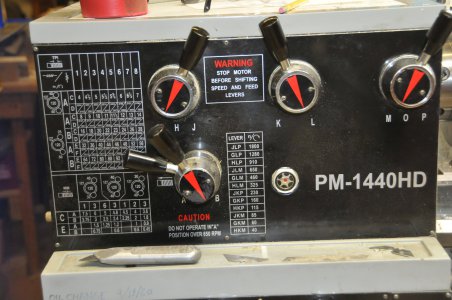
the left lower corner knob is what engages the connection to the knob labeled 1>8.
I have a couple of questions:
1) I do not under stand the function of the "left lower corner knob". If all that it does is turns off the function of knob 1-8 does this mean that in one position the lower left knob stops all the gear motion, i.e. the lead screw from turning and the Feed bar from turning? But isn't this what the "O" position on the C-D-O-E-F knob does? Having this knob and the O knob setting would seem to be functionally redundant.???
2) I would like to confirm what you said about the C-D-O-E-F. You should turn on the lathe and check, do not just rely on what the manual or chart shows. The answer is important to determine if there are any hidden threading values that can be reached via the gear box knobs.
i)---- In the O Position, neither the Lead screw nor the feed bar is turning?
ii)---- In the C and E positions, ONLY the Lead screw is turning?
iii)---- In the D and F positions, Only the feed bar is turning?
iv)---- What I am really asking is: Is any positions, of any set of levers and knobs, where the Lead screw the feed bar both turn at the same time? If they never turn at the same time then it appears that the lathe only has the one set of gears (1-8) where the non-factor of two rates are changing and all other conditions are just multiples of 2, or one must change the external gears to change the rates. The multiples of 2 show up in the charts via lever A-B (x2), or by changing from C-E (x4) of by changing the external gears by ratios of multiples of 2 (25T/50T Vs. 40T/40T) in the pictures of the charts). While the metric chart only shows a few values for any set of external gears, there are metric rates for each of the Knob positions (1-8), they are just not the standard values and are not listed in the charts. My spread sheet will generate then as well as all possible values using the external gears.
3) Is your PM-1440HD lead screw 8TPI?
4) The manuals imply that the external gears that came with the lathe were 25T, 30T, 32T, 40T, 50T plus the 120/127 exchange gear. Is this correct? Do you have others that should be put into the spread sheet?
5) I searched on 1440HD found a lot of search hits, but little new information. So the PM manual shows that the concentric levers (A-B lever in your photo of the top have of the lathe controls) has three positions for the outer handle not just two. Are there three positions, but only two letter labels. If so what does it do? So it appears the the manual I found on the PM1440HD at the PM site is not exactly your lathe! Is that the same manual that you have?
Comment: The feed and X-feed rates listed in the table are only good to 2-2.5 digits while the X-Feed rates are only good to 1.5-2 digits. The leading zeros do not count in the accuracy. Unless we know the exact gears and their arrangement in the carriage we can only use the numbers in the Feed/X-Feed tables to estimate the over all gear ratio. If you were to try to use the feed bar and and feed rates to make threads then the predicted accuracy would be no better.
Dave L.


 On this image columns 1 to 8
  are positions on the lower gear box. Gear positions and # of teeth are shown on the left side with 127 idler gear. Input on the top gear, out put on the lower gear. Leaver with position A or B is a doubler on the output of the main gear box. Lever positions C & E output the lower gear box to the threading shaft. Positions D & F out put to the feed shaft. #s above the diagonal line represent the carriage travel along the ways in "/rev of the spindle. #s below the line are cross feed movements "/per rev of the spindle.
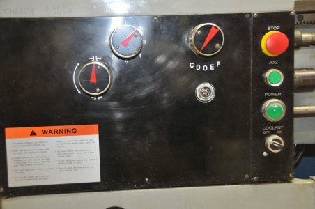
")