You have the gear head PM940M?
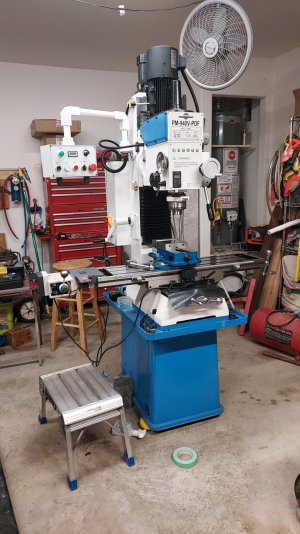
Yes, I have a PM940M-VS-CNC. It is one of the few fully CNC machines that PM sold. I am not for sure why but they did not sell them very long. I think the QC in China is poor and some machines have errors built in. Anyway, others have PM940M machines which they think are fine. Maybe the CNC versions came from somewhere else? But, not everyone is totally happy with the 940M. I have another friend who has the 940V and he did not have my problems. There is a long list of things on my machine which were done incorrectly. Some of these I have been able to correct. Others are still in the works. And yet others require considerable effort.
The VFD/motor turns the spindle between about 50-3200 rpm. I would like to go faster, but I am afraid of what it would do to the spindle bearings.
Over all I am able to use the machine and make lots of things. Maybe not as accurately as some would insist on. But most of my work does not demand great accuracy. I will not go through all of the things I have fixed or learned to live with, but here are a couple op issues.
So mine is a geared head and this is a poor design as it is too heavy for the vertical column. It has he head actually falls when you turn off the power. The CNC stepper cannot hold it unless there is power to it. So you increase the friction via the gib, but this is not good to do and causes backlash issues. Also, if the gib is not really, really, tight then the head rotates/tips (dynamic nod) as it goes up and down. I have it adjusted where there the backlash is minimized but the gib is still pretty tight. At this point if you have lowered the head and then start back up this rotation causes the tool to drop about ~ 0.001+" before it ever starts up at all. If you measure where it is suppose to be verses where it is you get a backlash of about 0.003". I actually think the head weight causes the way dovetails of the column to bow together effectively making the gib loose. I say that because if you tighten the gib to optimum when the head is in the middle of the column position (the region where the ball screw connects through the hole in the column then it is too tight to work well, or at all, when the head is all the way up or down. I plan to measure the dovetail spacing one of these days, but I need a measurement tool which will reach this distance and which will fit behind the spindle motor. I am in the process of building one. Because of all of this, for the CNC operation, I found that sometimes steps are missed in the z-axis and at the end of the process the head is lower than it is suppose to be. This was really bad when I first got the machine and I found that the gib was just poorly made and fitted even worst. It was binding. (fixed that somewhat). The best solution to this problem is to remove some or all of the head weight. Another back burner project!!
I have no idea if the dovetails are actually parallel or flat, but I found that the Y-axis dovetails are not parallel/flat at all as you move the table back and forth. It seems that the backlash in both the x and Y directions is on the scale of >0.003 and commonly worst. I was having trouble on the Y axis and when the table was the closest to the vertical column I measured the backlash and adjusted the gib to where it was tight, but not effecting the backlash. This yielded about 0.0025 to 0.003" backlash. However, I found that as I moved the table toward the front position (away from the column) the backlash went up linearly and then it just took off. I stopped the test when the backlash had reached >0.020. I was afraid I might crack the saddle! The y-axis through was reduced to about 6 inches. If I loosened the gib way up the backlash went back down to around 0.003". So I assumed that the doves tails flared apart (wider way) as the table moved away from the column. However.... I measured the ground reference surface between the dovetails a bit and found it was flat as far as I could tell. Since I did not have a way to measure the dovetail spacing yet, I measured the dept from the reference surface to the way's contact surface (were the saddle presses down on the way) using a digital dial indicator as a function of y distance. I found that this surface rose in the z direction considerably (several thousands) along the y-axis from the back to the front. This occurred on both sides of the way, but was much worst on the gib side. So I took off as much as 0.005" from this surface at the high end, and tried to taper it down as a function of y so that the surface was flat wrt the reference surface. I am not done, but because the metal is hardened it is slow going. This is a virtue as it causes me to take a lot of measurements and hopefully not over shoot. I have not even begun to work on the non-gib side. Of course, I probably need to go back and check the other side and take its highness off as well. This then leads one to ask if the x-axis nod has been changed or if it is a function of the y-position!!!? Likewise are the x-y motions perpendicular? Unknown at this point and there is no point in worrying about it much yet. However, if the y-axis dovetails were not parallel then one has to ask if this can be fixed at all. Anyway, after my working on the one side I have significantly removed the backlash and the table wobble to where I can use all of the y-axis motion. I realized that the only thing that matters is the squareness and the backlash. All the measurements and sanding of way material is to make those two things right.
Lots of other little things, like the E-stop being wired up backwards, but I will stop after these two examples.
PS. I purchased the 4th axis when I got the CNC. I do not use it much... maybe once when I was checking it out. I am thinking that if I connected it to the spindle shaft that sticks up when the quill is up.... via a pulley and disconnect the inductive motor temporally. Maybe I could write special G-code to do the powered tapping!! I could turn the tap at any speed and sync the z-axis motion. The code cannot be any harder than the threading workbook with its macros! One of these days....
Dave L.


")