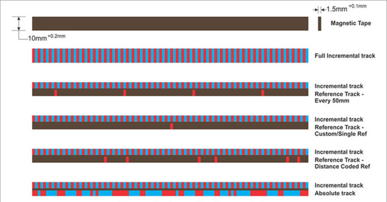
Taday I replaced the X axis scale on my Ditron 80 DRO. I was never really happy with the slim 1um magnetic scale though it was sure tiny and nice physically. Inconsistent diameter mode readings were frustrating, and I found that if I could locate an error, blowing off the scale of ferrous chips/dust would make it disappear. I blame the design for exposing the edge of the mag strip, not fully covered by the stainless top strip.
But the new generation of Ditron scales completely encloses the magnetics with three sides by the aluminum carrier and on the mag side by the stainless top strip that slides inside the extruded carrier. I think this will be much better.
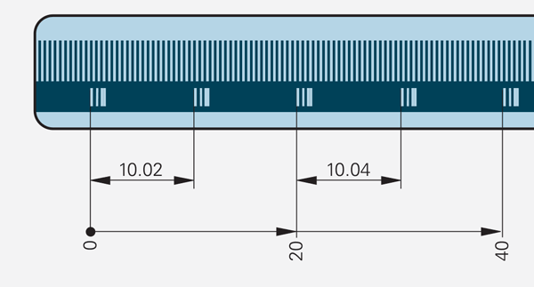
It’s an easier install than the older design, though every bracket and screw position is different. It’s in and linear calibrated, and against three 123 blocks, it’s as accurate as I can read the 0.0005 indicator.
I’ll report after I use it a bit.