Rockwell Delta 21-100 Restomod (not restore)

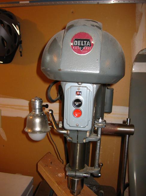
The original 3 phase 1/2 hp 1140rpm motor is secured to the housing and 4L size belt in place on the 2nd pulley for 470 spindle rpm. I will be using the KB Genesis VFD for motor control. I'm not sure how much I will be going over 60Hz with this 60+ year old motor, but with a vector duty motor I will probably top out at 100Hz. Having 4 of the original 6 pulleys, gives several options for mechanical advantage with the old motor, but with a proper vector duty motor pulleys 2 and 3 will probably be used most of the time.

The VFD enclosure is watertight with robust switches and speed pot, so no need for another enclosure with wiring. It is a "hybrid" model, digital electronics but with analog pots for various parameters which makes it easy to setup and adjust.

I've installed a 4 conductor plug and receptacle twist set between the motor and VFD. This way I can unplug it if the motor or VFD needs to be removed for any reason, or motor replacement for that matter. Nema L14-20.
_DSC2717.jpg
 
Last edited by a moderator:
There were 2 threaded holes on the left side of the column that I used for the VFD mount. I have one of these on my SB lathe, but it doesn't go in reverse because of the threaded spindle. Mills need to go in reverse so I will order an accessory switch to install in the front plate for forward-stop-reverse. There is also a cutout for an AC line power switch. As it is, I would have to pull the plug, but I would probably do that anyway.
_DSC2718.jpg
 
I've seen this arrangement on other mills, but don't think Rockwell had anything like this, where the foremost lever attached to the motor base aided in pushing the belt tight and the back lever tightened the lock screw, both controlled with one hand. The aluminum motor frame has been painted and except for the pending pulley cowl the head is pretty much done.
_DSC2719.jpg
 
The cowl or pulley housing is from a Rockwell Delta 14" drill Press model 14-000 from the 1960s and approximate vintage of this 21-100 vertical mill. In the top view there is a 1 1/2" clearance hole for the drawbar which is sitting an inch or so below. A new drawbar will need to be made with a longer nut to allow position above the cowl opening. I was planning a revised drawbar anyway because I have a method of installing a stop just above the R8 collet that is captive and upon unscrewing, the drawbar will push the r8 collet enough to release it. The lone cast iron cowl is an eBay find at a reasonable price and the materials to make this replacement pulley housing is less than $100, and arguably much more unique.
11544-A.jpg


_DSC2722.jpg_DSC2721.jpg
 
Been following from the begining and all I can say is wow! Nice job.
 
Thanks, Folks.

The drill press cowling has more than adequate height for the Rockwell 6 step pulley, even needing an extra long hex nut for the drawbar. I also wanted to apply the R8 collet release mod while I was at it. This eliminates the tapping of the drawbar to release a stuck R8 tool holder.
_DSC2727.jpg
Photo 2 shows the parts: The drawbar that came with the mill had a brazed screwed on hex nut which was removed, the 3/8" threads still good. The bottom of the drawbar has a 7/16" threaded on washer that, in the appropriate place will prohibit the drawbar from rising when unscrewing the hex nut, thereby pushing the R8 tool holder down and releasing it into ones hand. The position of the washer should be 1/8 to 1/4" above where the R8 holder is tightened down secure. To assemble, the drawbar is inserted up into the spindle from below and the special hex nut is fitted on. The fit doesn't need to be threaded, but a roll pin needs to be fitted thru the hex nut-drawbar to secure it. The roll pin can be seen in the upper end of the drawbar and the thru hole can be seen in the special hex nut.
_DSC2724.jpg
Photo 3 shows how it should look installed in the spindle, save for pushing the roll pin in. I've cold blackened the hex nut as I've done to most of the other levers and such. That is a 3/4" hex nut that I'm trying to use as a standard for some of the other cranks.
_DSC2728.jpg
 
The table is the last big part of this build. I had previously filled 3 or 4 drill holes and now scrapped the surface. The table had a high spot or hill right in the middle, as indicated by a surface plate spinning at its center. The scrapping required to flatten, also allowed the removal of much surface damage. The only things left to do is rebuild a cast iron x axis wheel and build a z knee crank.

Oh, and I recently saw a quill quick lever handle return mechanism that I will try and detail.

I hope to compare and contrast this Rockwell knee mill with my square column bench gear head mill as to workpiece size capabilities and other features. I like the concept of a stationary spindle head with movable knee as the work space stays basically the same regardless of size. The bench mill head movements result in sitting down for short workpieces and standing for taller workpieces.

And I've gotten used to the 9" by 32" table of the bench mill versus the smaller 6x24" Rockwell table meaning the work envelope is larger. Has that size 21-100 table been a problem for other Rockwell users as far as heavier machining?
_DSC2766.jpg
 
That's beautiful work, very impressive!

-Bear
 
You always wish for more table
I've only had to move stuff a few times on my Rockwell.

Sent from my SM-G715A using Tapatalk
 
Back
Top