

-
Welcome back Guest! Did you know you can mentor other members here at H-M? If not, please check out our Relaunch of Hobby Machinist Mentoring Program!
You are using an out of date browser. It may not display this or other websites correctly.
You should upgrade or use an alternative browser.
You should upgrade or use an alternative browser.
Rotary table/indexer controller.
- Thread starter EricB
- Start date
- Joined
- Apr 30, 2015
- Messages
- 11,317
If your motor is getting too hot you should be able to set the holding current on your driver.
I'm using a DRV8825 driver chip which has a current set adjustment
You should be able to leave the stepper powered for hours without getting too hot
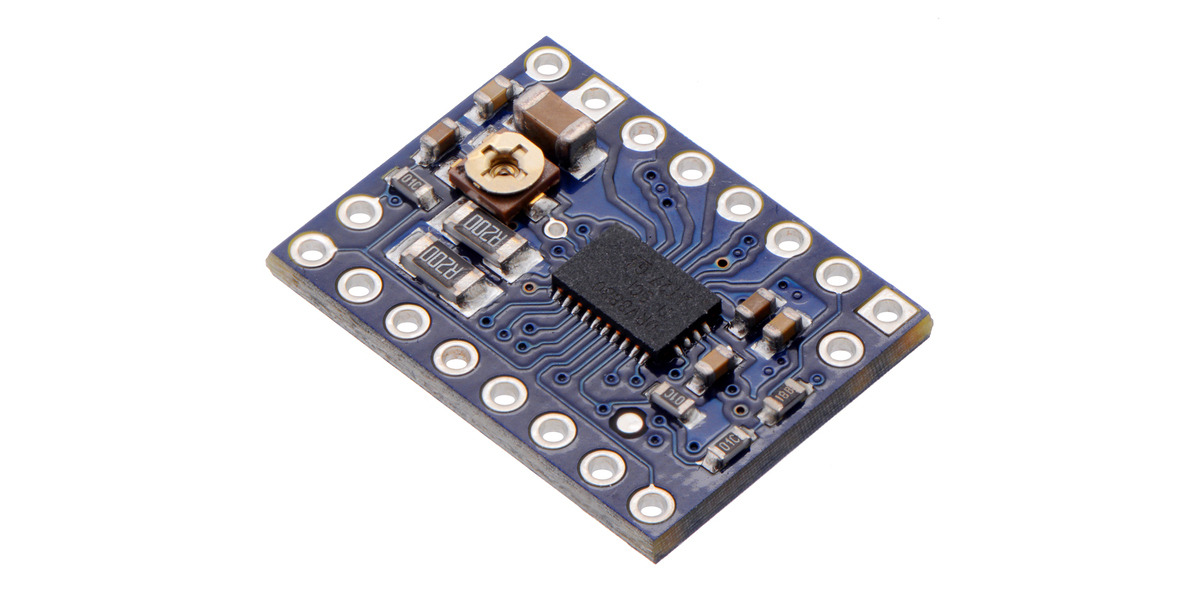
 www.pololu.com
I'm using a DRV8825 driver chip which has a current set adjustment
You should be able to leave the stepper powered for hours without getting too hot
Pololu - Stepper Motor Drivers
With features like adjustable current limiting and selectable microstep resolutions, these drivers make it easy to get a stepper motor running with simple step and direction control interfaces.
www.pololu.com
Last edited:
- Joined
- Feb 15, 2020
- Messages
- 375
The motor is cool. The driver chip is cooking breakfast. It's curious because the Sherline driver boards have no heat sinks on the chips.
The driver I'm playing with now is an L298N "H" bridge, because that's what I have on hand. It is capable of driving a load up to 4 amps and I can adjust the current limiting. I just have to cut some traces and add resistors. What size resistors is arcane knowledge not included in the data sheets. I guess it's trail and error until I get what I want.
Some drivers can reduce motor current after a timeout period. I'm looking into how to do that.
I have several other drivers coming to experiment with later.
The fun part for me is the software. So many different ways to solve the problem!
- Joined
- Feb 15, 2020
- Messages
- 375
I made a video when I initially tested the motor. For power I used a 9 volt transistor battery, so not a lot of current. Looking back at it, the LEDs on the driver board dim when the motor is stopped. That tells me the holding current is much higher than the moving current. Makes sense since the coils are pulsed they're not drawing full current when the motor is moving.
Hmmmm...
Hmmmm...
- Joined
- Apr 30, 2015
- Messages
- 11,317

- Joined
- Feb 15, 2020
- Messages
- 375
I've made some progress toward a functioning controller. So far I have two modes. The degree mode works good.
The division mode gets the math wrong for counts that are not factors of the stepper/table combination, so it looses several degrees by the time you make a full circle. It always comes out right on the screen but the motor and the screen don't match.
It does work and drives the table. I had it going for several hours today trying various methods, and check the accuracy. I was starting to make a video when I let the smoke out of my power supply.
Here's what I have so far. This is just the test setup. The parts will be changed for the final version.

Here is the video I was working on before the smoke.
Eric
The division mode gets the math wrong for counts that are not factors of the stepper/table combination, so it looses several degrees by the time you make a full circle. It always comes out right on the screen but the motor and the screen don't match.
It does work and drives the table. I had it going for several hours today trying various methods, and check the accuracy. I was starting to make a video when I let the smoke out of my power supply.
Here's what I have so far. This is just the test setup. The parts will be changed for the final version.
Here is the video I was working on before the smoke.
Eric
- Joined
- Feb 1, 2015
- Messages
- 9,610
RT's are unique in that they use a worm drive. Worm gears cannot be back driven so holding current can be set at a minimum. Additionally, the 90:1 gearing provides tremendous mechanical advantage so a high drive current isn't necessary. I have a Tormach 4th axis based on the Phase II 6' RT. There is no rating plate on the motor but it is a Nema 23 frame and the drive current is set for a maximum of 2.6 amps.
- Joined
- Feb 15, 2020
- Messages
- 375
I've found in the spec sheets that some of the better driver chips reduce holding current automatically after a short timeout period. It's easy enough for me to just toggle the enable lines to the driver after the motor stops. I think that once I get a proper power supply I'll be fine. I was trying to pull almost 3 amps from a 1 amp wall transformer. It worked for a few hours.
- Joined
- Apr 30, 2015
- Messages
- 11,317
Try some other driver chips- you'd be surprised how little current you really need