Rotary table/indexer controller.

Try some other driver chips- you'd be surprised how little current you really need
I received a TB6560 driver today, and I have some other choices coming soon. My new power supply is on order too.

The L298N driver I'm using can take the load. It's rated for up to 46 volts at 4 amps. I solved its temp problem with a cooling fan. The motor needs 24 volts and draws 1.4 amps per coil to hold, so that's 2.8 amps total. I can limit the current with some added resistors. Just ain't got there yet.

I looked over your code and the original version I started with was identical in some parts, so it must be in common use. I don't recall where I got my copy.

The discussion on the other message board presents some of the same questions I've asked myself about accuracy of divisions. I didn't see any solutions and I'm still working it out. My interim solution for handling division counts that are not factors of the table ratio and motor step count is let the controller do the math and make the move, then disable the driver so I can manually correct the final position with the hand wheel. Still easier than figuring it all out for each division on a manual table.
 
The code knows how to add or subtract steps so that odd numbers and primes come out correctly- That's the high-falutin' math portion that was
a bit beyond my skill level, so I borrowed the code from a better mathematician than me.
If the code initialization is set correctly for the number of steps/div and the gear ratio then no manual intervention should be required

"Sometimes a man's got to know his limitations" Clint Eastwood
 
Last edited:
The code knows how to add or subtract steps so that odd numbers and primes come out correctly- That's the high-falutin' math portion that was
a bit beyond my skill level, so I borrowed the code from a better mathematician than me.
If the code initialization is set correctly for the number of steps/div and the gear ratio then no manual intervention should be required

"Sometimes a man's got to know his limitations" Clint Eastwood

We must not be looking at the same code. The file I downloaded is called "Arduino_Rotary_Table_Control_2016". Is there another?

Eric
 
Did you use the one from the "Rotary table for Dummies" article?
I can post the Arduino file here if you want to compare- mine says 2017 beta but I remember having to make a slight change regarding the
pinout of the keypad being reversed

Hmm, seems like I'm having trouble trying to post a .ino file- need to cogitate for a bit
 
Last edited:
Did you use the one from the "Rotary table for Dummies" article?
I can post the Arduino file here if you want to compare- mine says 2017 beta but I remember having to make a slight change regarding the
pinout of the keypad being reversed

Hmm, seems like I'm having trouble trying to post a .ino file- need to cogitate for a bit
Give me your email and I can try to send it that way
Depending on length, you could cut and paste the ino code using code icon </>. You could call it C++ and the formatting would come out ok. Sort of like this:
C++:
#include <SPI.h>
#include <WiFi101.h>
#include <Wire.h>
#include <Adafruit_GFX.h>
#include <Adafruit_SSD1306.h>

Adafruit_SSD1306 display = Adafruit_SSD1306();

#if defined(ESP8266)
  #define BUTTON_A 0
  #define BUTTON_B 16
  #define BUTTON_C 2
  #define LED      0
#elif defined(ARDUINO_STM32F2_FEATHER)
  #define BUTTON_A PA15
  #define BUTTON_B PC7
  #define BUTTON_C PC5
  #define LED PB5
#elif defined(TEENSYDUINO)
  #define BUTTON_A 4
  #define BUTTON_B 3
  #define BUTTON_C 8
  #define LED 13
#else
  #define BUTTON_A 9
  #define BUTTON_B 6
  #define BUTTON_C 5
  #define LED      13
#endif

#if (SSD1306_LCDHEIGHT != 32)
 #error("Height incorrect, please fix Adafruit_SSD1306.h!");
#endif

int pingPin = 13;
int inPin = 12;
long microseconds;
int16_t xx, yy;
void setup() {
  // put your setup code here, to run once:
  pinMode(pingPin, OUTPUT);
  pinMode(inPin, INPUT);
  //Configure pins for Adafruit ATWINC1500 Feather
  WiFi.setPins(8,7,4,2);
  display.begin(SSD1306_SWITCHCAPVCC, 0x3C);  // initialize with the I2C addr 0x3C (for the 128x32)
  Serial.begin(9600);
  display.display();
  delay(1000);
  // Clear the buffer.
  display.clearDisplay();
  display.display();
   // text display tests
  display.setTextSize(2);
  display.setTextColor(WHITE);
  display.setCursor(0,0);
 
  //display.println("Pinger:");
  //xx = display.getCursorX();  // returns with x value of cursor
  //yy = display.getCursorY();
  display.display();
}

void loop() {
  // put your main code here, to run repeatedly:
  long duration, inches, cm;
  digitalWrite(pingPin, LOW);
  delayMicroseconds(2);
  digitalWrite(pingPin, HIGH);
  delayMicroseconds(10);
  digitalWrite(pingPin, LOW);
  delayMicroseconds(2);
  duration = pulseIn(inPin, HIGH);

  cm = usToCm(duration);
  Serial.print(cm);
  Serial.println(" cm");

  delay(500);              // ping once a second
  display.clearDisplay();   // clear display and rewrite
  display.display();
  display.setCursor(0,0);   // make sure the cursor points to 0,0, the top left of screen
 
  //display.println("Pinger:");
  //display.print("Rng: ");
  display.print(cm);
  display.println(" cm");
 
  display.display();
}

long usToCm(long microseconds){ return microseconds/58;
}
 
It's the forum software that's the holdup- let me try renaming it as a .txt file- change the filename back to .ino when you get it
 

Attachments

  • Dummies_Rotary_Table_Control_2017_beta_GOOD_VERcopy_.txt
    8.6 KB · Views: 6
I think that worked
I seem to remember that the final, truly full-featured code was a couple revisions in from the first one posted in the article.
When I verified that it was in fact ok, I made a few comments so I could recognize it easily. MS is me, not the original author.
I found that the author suddenly swapped the keypad pinout so I swapped it back. It took me some time to figure out the I2C address for the LCD
There is a tool "I2C scanner" I believe in both the Arduino repository and in the article
-M
 
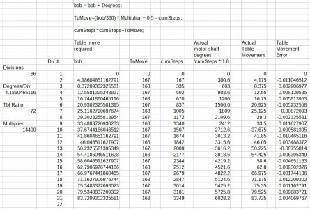
Here is the relevant portion:
{
bob = bob + Degrees;

ToMove=(bob/360) * Multiplier + 0.5 - cumSteps;

cumSteps=cumSteps+ToMove;
}

I had to make a spreadsheet to prove it to myself but that's a simple and effective solution!

division algorithm.jpg

Thanks!
 
It may look simple to you but I couldn't even conceive of the algorithm to do it let alone convert it into code to execute it- I'm glad it meets
your approval :) I'm more of a hardware guy than a software guy
Hats off to the original author(s) I think it was a collaborative effort
 
I was heading in that direction, adding a half step every so often (or extra degrees), but had not figured out the how many and when or how to keep track of them.

I'm using a library function to drive the motor so I'll probably have to change that. It takes a degree input rather than a step count, and I don't know if it performs any error correction. Assuming it doesn't, I can still use your algorithm by multiplying "ToMove" by the degrees/step of the motor (1.8) to get the input in degrees for my function.

It could work. Hmmm...

Eric
 
Back
Top