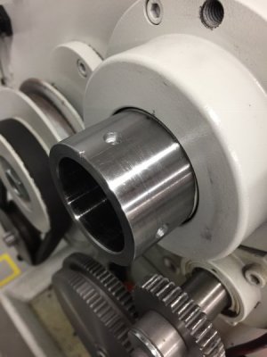
Setting-up the PM 1236-T Lathe

Sorry, this is the Kit view with the cut down panel that I intended to insert:

DFCBE6A0-89C1-4310-8A74-A63E202DB837.jpeg
 
D.) Sliding Chuck Shelves- this is the last section on tool storage.

481BB5D4-5F7E-4304-891A-CFE605E7C85B.jpeg

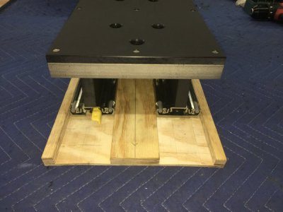
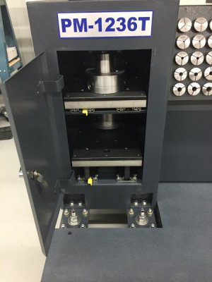
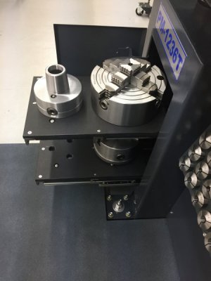
The lathe stand columns have two shelves welded in place. I found this to be an inefficient use of space; you can only put things in as wide as the door opening and every time you need something in the back you have to take out everything in front of it. So, I decided to use the left column for my chuck storage. To do this I made some HDPE(high density polyethylene) shelves and mounted them to Accuride extra heavy duty full extension drawer slides. They hold up to four D1-4 chucks.

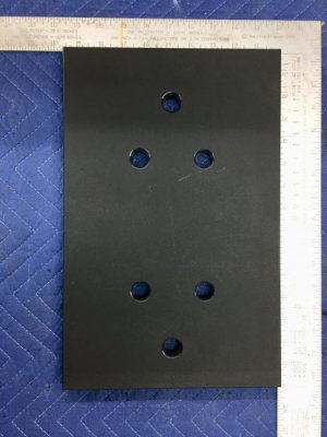
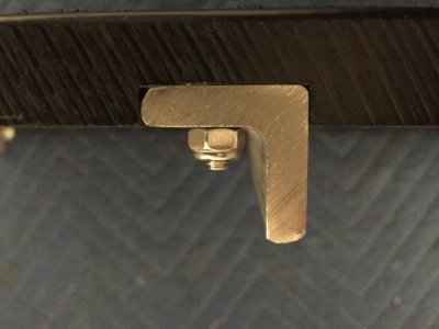
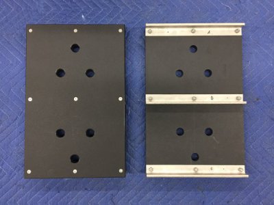
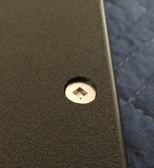
The first step was to make the HDPE plastic shelves. I used HDPE because it would not mar the back surface of the chucks and would not rust. I used 3/4” black Starboard and cut them to 9-1/2”x15”. I drilled and chamfered two sets of holes for my D1-4 chucks. I added stainless steel angle transversely on the bottom side to increase rigidity. These were attached with countersunk screws, again, to protect the back surface of the chucks.

7D435DED-12DA-4B84-BC98-72233F7006D8.jpeg. B3856882-8DDB-43C8-8912-99B7210A0721.jpeg

58116ED7-67A7-40B9-9E7F-0EA6F3C5FF50.jpeg. 5EEAAEB5-E769-4C78-9A2D-8DFAADB31701.jpeg

087BF337-AA5F-43A9-9E0A-F213034DFF9D.jpeg

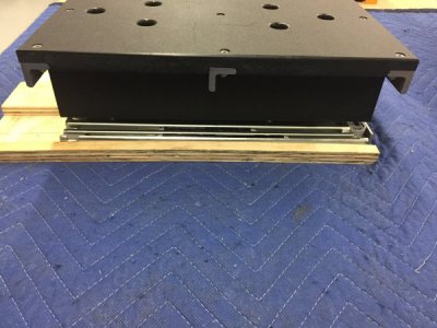
I then made longitudinal supports for each shelf to raise it to a level that would clear the door hinge. This was taller for the lower shelf. These supports are at the same width, and will attach to, the slides.

22866E28-C9A5-4E1D-9CF4-E1047A16EA6F.jpeg. 42B8FC4A-4FC4-42B6-9958-597E6881373E.jpeg

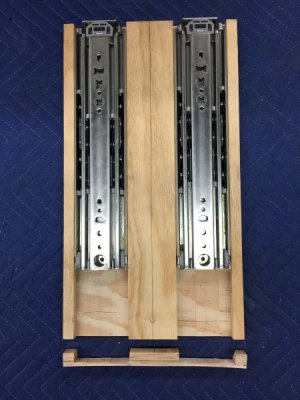
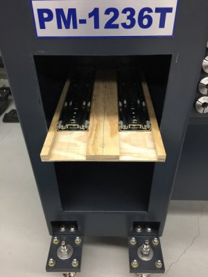
I then made a jig out of plywood that was the same width as the door opening and would hold the glides perfectly parallel for marking the mounting holes on the stand shelves. I took the time to do this since I did not want any toe-in with the slides which would limit the full extension of the slides. I used a dado blade on a table saw to make the jig.

11502E84-D47E-40D2-9BD6-C5211C909883.jpeg. 7FB2C466-C8FD-46A0-9A15-D1AD9C758831.jpeg

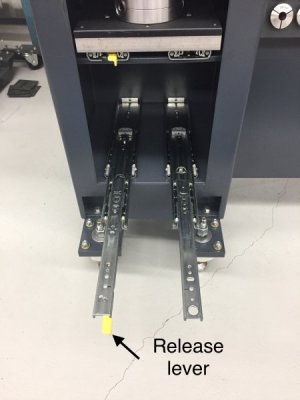
Just a little bit about the slides. They are 14” extra heavy duty full extension slides(model 9308E14) that have a lock-in and lock-out feature activated by a yellow lever on the front of the slide. They are rated for 600lb in the usual vertical position however their rating drops to 180 lb in the flat mounting. Plenty for my chucks. Also, the lock-out feature does not work in the flat mount position since it is gravity activated. This was OK with me since I was really most concerned about the shelves being locked in place in the retracted position. Since I move my lathe occasionally I didn’t want the door coming open and the shelves unexpectedly extending.

4B2D2700-3B41-4C5E-B029-C3709E454D08.jpeg

Finished:

8522477A-C1FF-489A-80FA-977F9B1BC518.jpeg

46EAB9B6-117D-45D4-ADCA-A2A1A77BD198.jpeg

Well, that finishes what I did for tool storage on the 1236-T. Next is a Miscellaneous section. The first item is something I use a lot and is my first experience with an interference or shrink fit of two parts.
 
The reason you got two panels is that they mount front to back and give a little depth to the racking such that the collets don’t wobble (if that is a term I can use, but you get the idea) when they are mounted as a stand-alone stand. When you mounted it on your frame the second panel wasn’t needed to stabilize the rack.
 
My set of 5C collets, also from PM, didn't come with the rack. I prefer to keep them in a clean location, a drawer. I've got a lot of Star board and UHMW from .75 to 3" thick left from jobs in the shop. That stuff comes in handy for a lot of things. My tool holder rack is also a pc. of Unistrut but I just beveled the edge on the mill and hang the toolholders directly on that. I like your solution better since each holder takes up less space. I've now got 18 tool holders and need to make a more dense rack. I also need to get another roll around tool chest.
We use a lot of Accuride slides. When they first moved manufacturing to Mexico there were a lot of quality problems but much better now.
I'm considering buying an 8" rotary table for the mill, any experience with them?
 
The reason you got two panels is that they mount front to back and give a little depth to the racking such that the collets don’t wobble (if that is a term I can use, but you get the idea) when they are mounted as a stand-alone stand. When you mounted it on your frame the second panel wasn’t needed to stabilize the rack.

Thanks Firstgear! That makes sense.
 
My set of 5C collets, also from PM, didn't come with the rack. I prefer to keep them in a clean location, a drawer. I've got a lot of Star board and UHMW from .75 to 3" thick left from jobs in the shop. That stuff comes in handy for a lot of things. My tool holder rack is also a pc. of Unistrut but I just beveled the edge on the mill and hang the toolholders directly on that. I like your solution better since each holder takes up less space. I've now got 18 tool holders and need to make a more dense rack. I also need to get another roll around tool chest.
We use a lot of Accuride slides. When they first moved manufacturing to Mexico there were a lot of quality problems but much better now.
I'm considering buying an 8" rotary table for the mill, any experience with them?

Larry42, I use Starboard frequently also. It is nice that one can use woodworking tools with it but I am always surprised at how much it costs. We have a plastics company in town that sells scraps from their big jobs. I usually check there before I buy elsewhere.

I can’t quite picture what you do with your Unistrut. If you have a chance send me a photo.

The Accuride was the only manufacturer that I could find that had very heavy duty full extension slides that weren’t incredibly expensive(hundreds of dollars). The Accurides have worked very well and do not seem to sag at all even with the 8” 4JC and 6” 3JC on the same shelf.

Sorry, not much help with the rotary table. I bought a small, inexpensive rotary table from Grizzly for a project I was working on a while back but have not used it since.
 
IV). Miscellaneous
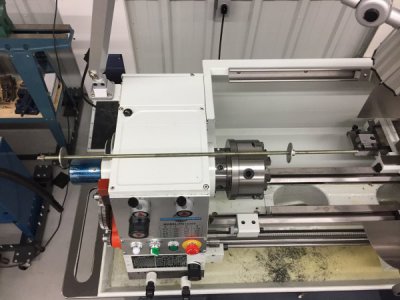
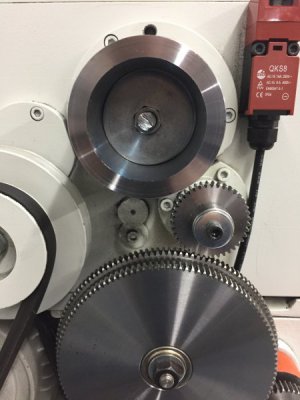
A. Headstock Handwheel- this addition to the P 1236-T has been very useful. I use it frequently, for example, when I am changing gears to help the gears mesh, when I am moving the chuck repeatedly when centering a work piece in the 4JC and, although it is probably considered bad practice, I use my hand on the handwheel to slow down the lathe at the end of an operation. For me, it is better than doing these things by grabbing the chuck. Although this is a pretty straightforward project it took me quite a while; it would be nice if PM had this as an option.

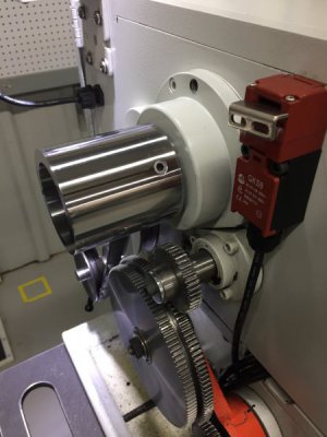
For this project I took a 10” aluminum wheel and balanced it, bored it out to match the ID of my spindle bore and then attached it to the spindle with an adapter sleeve. I attached the adapter with set screws on the spindle side and a shrink fit on the wheel side. The kit view below is deceptively simple; this project took me most of a weekend but I do like the result.
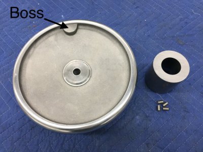
E8A49DB3-4DBC-4CE4-8ED4-FC084305B792.jpeg

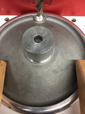
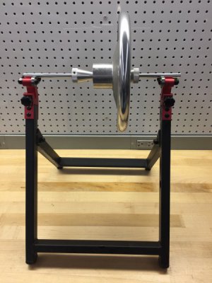
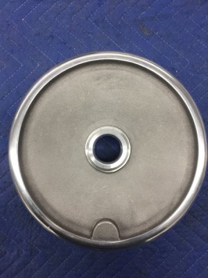
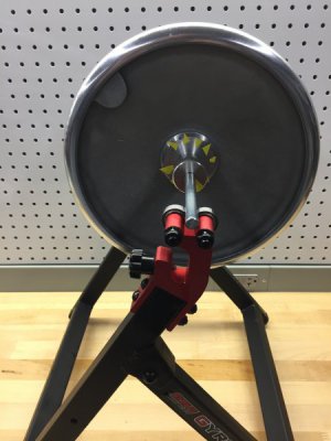
The Wheel- I ordered several wheels from McMaster-Carr; the one that looked the best was a 10” spokeless aluminum handwheel with a 5/8” unthreaded through hole and 2-1/4” OD hub(MC 8515K53). Unfortunately, all wheels from MC that I considered have a boss on them for attaching a handle, I would guess. I was concerned that this would cause the wheel to be unbalanced and cause vibration on the lathe. I put the wheel on a bicycle wheel balancer and not surprisingly found it to be unbalanced To balance the wheel I drilled out the boss, checked it on the balancer, drilled out more and rechecked it until the wheel was balanced.
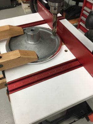
C2193412-579E-4815-A270-23D2730C07C8.jpeg. 524B1E59-659D-4F66-9B01-36088C78552E.jpeg

B8FE075B-2B22-48B9-A618-D38E98DD827E.jpeg. 77411F07-6D7B-443F-B1AC-A6A63DB6EB55.jpeg

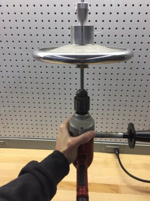
Each piece of tape marks where the wheel stopped. The random arrangement indicates it is balanced. I put it on a hand drill to test for balance.
542A15DB-0B3B-4584-B1F8-0747E2802E66.jpeg. CBDDD0E1-CD6E-4222-A1B9-65397FC1EB4F.jpeg

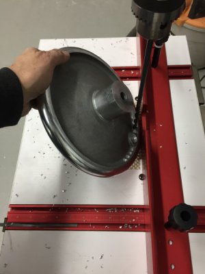
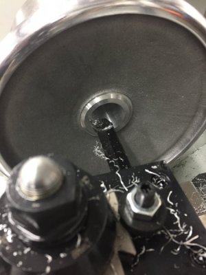
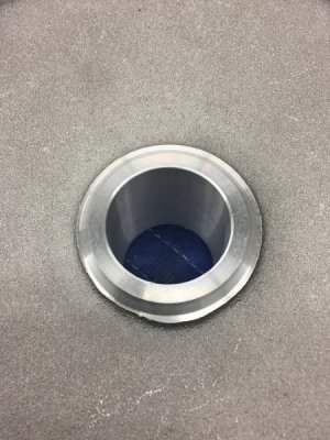
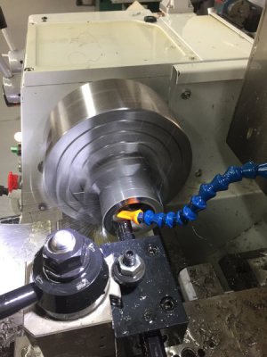
Next I drilled, then bored the through hole of the wheel to match the diameter of the spindle bore. I didn’t want to lose any of the generous 1-9/16” spindle bore of the 1236-T.
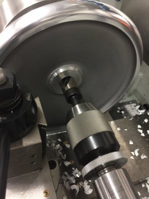
4FF61220-BF27-4868-97BA-65C8598B27DB.jpeg. 5A1140BE-C8A9-4582-8546-7FDD7F6016FA.jpeg

D5A79FB0-0F04-4264-9FF0-F7A7B7C1517B.jpeg. 3A9A6343-340A-43E9-93A0-4CE0F554A988.jpeg

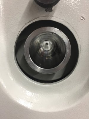
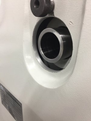
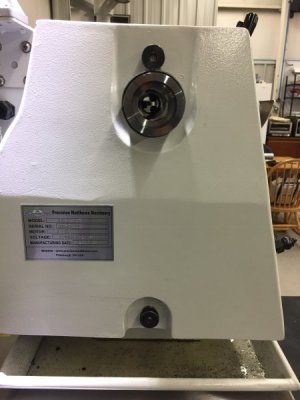
Next, I enlarged the hole in the lathe cover. The hole on the cover was eccentric and too small to accept the adapter collar that I was planning on making next so I enlarged the hole using a spindle sander.
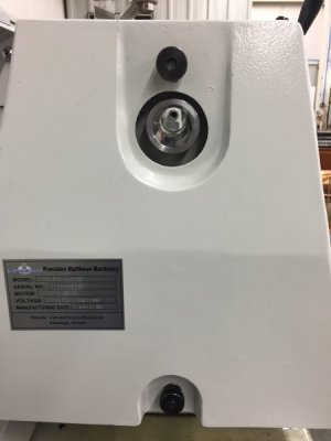
C3FC38CF-FC5A-4DF7-91D4-BF8ED8895E5D.jpeg. 84FACE4D-A856-4446-836B-D27009F46269.jpeg

ECF4DD8F-EE0F-40EA-9BC0-179F3CE0BEAC.jpeg. DCA2F325-F203-4BC2-9326-42770CD833CD.jpeg

DC4C8549-1158-42A3-BA76-F6CAF6C0E619.jpeg

So that finishes the modifications of the wheel, next is making the adapter sleeve.

Since I am still a bit concerned about losing the post due to the website problems I am going to post this and then go on to making the adapter sleeve in the next post.
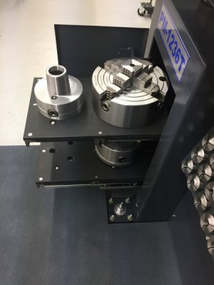
 
I usually start a section with an overall view of the finished project. I forgot to do that for this project so here is where I am headed:

123E3472-CC5A-42FB-9426-DD7AC6A21AAA.jpeg
 
Now, on to the adapter sleeve. The adapter is just a stainless tube bored at either end to the diameters needed to fit over the spindle on one end and over the handwheel hub on the other end. I left a shoulder internally to act as a stop for the spindle and hub. This was a real test for me as a newbie. I really needed to nail the IDs of the adapter for the spindle and handwheel sides and I had very little experience boring. All turned out well, but I wish I had read Mikey’s Primer on Boring before this project. I WANTED a really close fit on the spindle side, where the adapter was attached by set screws, to eliminate any slop that might cause vibration but I HAD TO have the correct ID on the handwheel/shrink-fit side or I would have to start over. I started with a 3” length of 2-3/4”x1-1/2” 304 stainless tube from Speedy Metals.

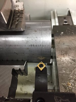
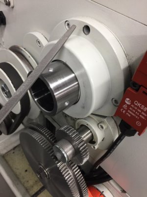
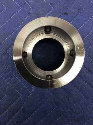
The spindle end: after I got the tube centered on the 4JC I faced the tube then put a scratch mark exactly where I wanted the set screws. I then bored the end of the tube, again, leaving a shoulder internally to act as a stop for when I slipped the tube over the spindle. I was able to hit the diameter where I wanted but it was a bit tight, so rather than take my chances on getting the piece repositioned exactly the same on the 4JC I chose to very lightly file the OD of the spindle until there was a nice fit:

F2F3EF18-5C98-411B-B82C-2492222723D7.jpeg. 4148EB7A-38DC-4816-B41B-6CBCB64370B3.jpeg

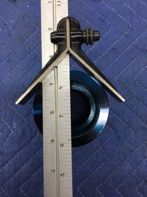
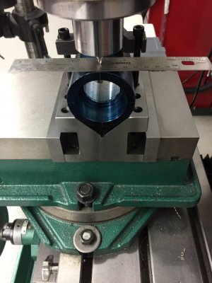
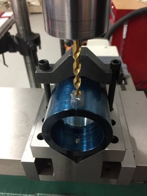
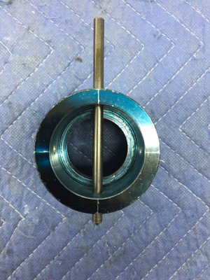
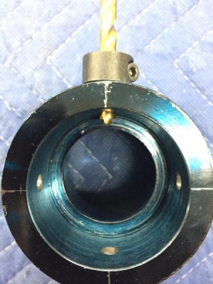
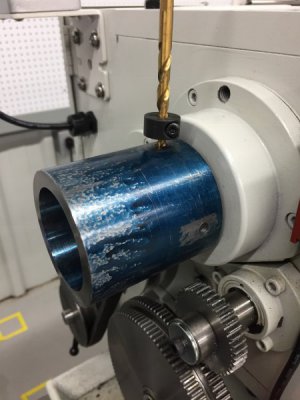
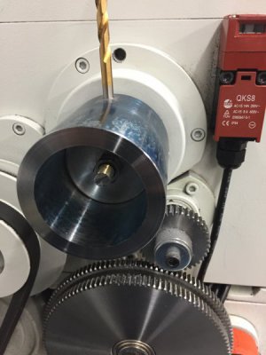
I blued the adapter for marking of the four holes that I would drill for the set screws at the position of the scratch mark made earlier. I used four holes instead of three since I thought I would allow me to do some fine tuning of the adapter on the spindle using the set screws like a 4JC. Using a center drill followed by 1/4” drill I drilled them one at a time rather than drill across the piece on one pass. I did this because I thought if I was off center with the first hole the error would be carried over and to the second hole. It worked out well and I could easily pass a center punch through the holes indicating that they are lined up but if anyone has an easier way please let me know.

D56BA45A-9436-460D-8162-3EDF71F090F6.jpeg. 0EAFDB82-D5E2-4022-8EE4-9A871DA6E562.jpeg

4FE0295E-8DFC-4490-B56D-3FF6D6F1A39C.jpeg. 639AAB7E-F1DD-42BD-8E0C-37FCB2E1B411.jpeg

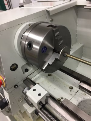
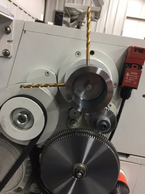
I then put the adapter on the spindle and used all-thread rod (passing through the spindle), washers and nuts to hold it firmly in place while I used the holes in the adapter as guides for drilling flat bottom holes in the spindle. These flat bottom holes would act as recesses for the set screws. I put a witness mark on the spindle and adapter so that I would be sure all lined up in the future, however they turned out that the holes line up in all positions.

CF883A20-260B-4AE7-B9F8-8F91898EC97E.jpeg. 6B0C765F-DE99-42DB-9CCB-AEA63BED11E4.jpeg

63098403-AAA6-4E63-B2EA-A69740F9B676.jpeg. AF4BA6D0-EA8D-4B91-853B-DF76A0A522FB.jpeg

6902A41B-CE3E-495C-A0AD-79195D2AA83F.jpeg. C39F8AA4-38AC-49FF-A3E0-B888B7854B58.jpeg

AEC49601-FCA8-4F4A-B99F-64AF5FEDB084.jpeg. B82F92E0-5E77-4F44-844D-6C66A1C92175.jpeg

B82F92E0-5E77-4F44-844D-6C66A1C92175.jpeg

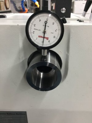
I then took the adapter off, threaded the holes to 3/8”-24 for the blunt tip set screws, and checked the TIR and was surprised to find it to be 0.0001-every dog has his day!

AFB9D460-EFA7-4467-B189-B42815595FE0.jpeg. DCB43BB1-C2AD-40EB-B778-6D01A5ED56C0.jpeg

06229FBB-D1E9-404B-8567-301F4A17AE39.jpeg. 46944E92-1219-4B42-9CFB-8891B80FF1F9.jpeg

Will post this now and do the handwheel end of adapter and then the shrink interference fit of the handwheel to the adapter.

60004871-59F2-40DD-AB9B-E7FE47C79A3F.jpeg
 
Interesting that the end of your lathe's spindle is not threaded. The thru bore on my lathe is about the same diameter as yours, wish it was larger.
I made a spider for the outboard end of mine to support long work. I failed to do it the correct way and it took me a long frustrating time. Lesson learned, maybe. I should have made a threaded piece the same as the end of the spindle that I could use as a test fit part while the spider was still chucked up. As it was I had to take the part out and test fit it to the spindle, TOO TIGIHT! Then I had to re-center it and get the thread to track the same. It's hard enough to do that on an external thread but this was a quite fine, internal. This project also required stopping a bore at the correct depth so it would butt against the end of the spindle when tightening the spider. Got to love those DROs.
 
Back
Top